Using Feature Modifiers

What is Feature Modifiers?

Feature Modifiers are Functional Features that modify shape or functional features. Feature Modifiers alter selected features, more precisely their shapes, by adding or subtracting material from them.

Feature Modifiers Types

The following are the different Feature Modifiers:

  Cut
  Remove
  Intersect
  Transform
  Mirror
  Offset
  Pattern
  Edge Fillet
  Variable Radius Fillet
  Face Face Fillet
  Tritangent Fillet
  Chamfer
  Draft Angle
  Variable Angle Draft

 Understanding of Feature Modifiers

Feature Modifier Chain

You can add Functional Modifiers by selecting the features such as Prisms to modify with the elements such as Surfaces. As additional Feature Modifiers affect the geometry, a localized modifier chain is formed. Each modifier affects the feature directly beneath it in the chain. However despite any modifications, geometry traces to the originating feature.

Feature Modifiers are added to the top of the modifier chain of the Functional Feature that is selected as their target. Once the Feature Modifier is inserted into the chain, its position is fixed unless its current parent/child relationship is broken. Features that are modified have a modification overlay () applied to their icon in the Specification Tree.

Feature Modifier Rules

The rules that are used to form a Feature Modifier chain are:

  1. A Functional Feature can have only a single Feature Modifier as its immediate parent.

  2. A new Feature Modifier is inserted on top of the highest active modifier in the selected target’s chain.

  3. A Functional Feature may be a target of a Feature Modifier if it is not currently a target (i.e. it does not have a modifier as a parent). Or it and the Feature Modifier that selected it must have the same parent.

  4. The position of a Feature Modifier within its chain can be modified only if it becomes the target of a sibling Feature Modifier. For example if a Pattern feature modifier selects a Fillet feature modifier that is its sibling, the current parent/child relation of the Fillet will be broken. The Fillet feature modifier will then become the child of the Pattern feature modifier.

  5. If a Feature Modifier is moved within the chain, any immediate children and their branches not in the selected chain are also moved.

  6. A Functional Feature cannot be the target of a Feature Modifier if its inclusion in the chain at that position would cause Feature Modifiers, regardless of their activation status, above it in the chain to have more leaf target Functional Features that they are allowed. For example, some functional modifiers, such as the Functional Fillet, allow only a single leaf target.
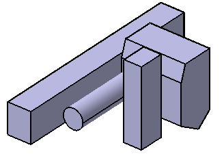
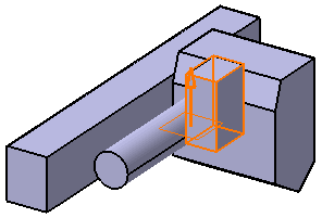
Open the Feature_Modifier.CATPart document.
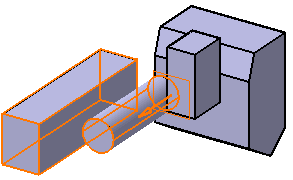
The part has four Shellable Prisms. You will add 3 Feature Modifiers (3 Cuts in this example)
  1. Click the Cut icon .

  2. Select Shellable Prism.1 for Features to cut. And select xy plane for Cutting element. Click OK. Select Shellable Prism.1 in the specification tree and select Parents/Children... in the contextual menu. Parents and Children dialog appears with the relationship.

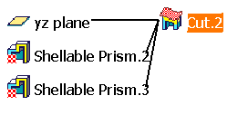
  3. Click Cut icon and select Shellable Prism.2 and Shellable Prism.3 for Features to cut. And select cut 2 plane for Cutting element. Select Cut.2 to see Parents/Children relationship.

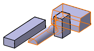
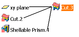
  4. Click Cut icon and select Shellable Prism.2 and  Shellable Prism.4 for Features to cut. And select xy plane for Cutting element. You will notice when Shellable Prism.2 is selected, Cut.2 is selected instead. Also you cannot select Shellable Prism.3. This is because Cut.2 is the top of the chain of Shellable Prism.3 and Cut.2 is already in the list of Features to cut. Consequently, Cut.2 cannot be inserted a second time. You will notice Cut.2 has a modification overlay icon applied in the specification tree. Select Cut.3 to see Parents/Children relationship.

  5. Select Cut.2 in the specification tree. Select Cut.2 object in the contextual menu and select Deactivate menu. Do the same for Cut.3.

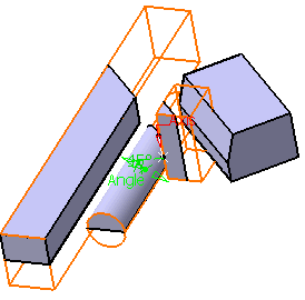
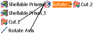
  6. Click Transform icon and click Rotation icon tab. Select Shellable Prism.2, Shellable Prism.3, and Cut.1 as the features to be transformed. And select Rotate Axis for Axis and enter 45 degree. Activate Cut.2 and Cut.3. Select Rotate.1 to see Parents/Children relationship.

  7. You will see that Rotate.1 is applied to Shellable Prism.2, Shellable Prism.3 and Cut.1 before it is modified by Cut.2.

  8. Deactivate Cut.3 and Rotate.1 in the specification tree.

  9. Select Transform icon and click Scale icon tab.

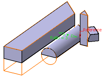
  10. Select Shellable Prism.3 for Features to transform. You will notice that Cut.2 is automatically selected.

  11. Select Point.1 for Reference.

  12. Enter 3 as the ratio scaling value. Click OK.

  13. Activate Rotate.1 and Cut.3. Select Scale.2 to see Parents/Children relationship.

  14. You will notice that Scaling.2 is applied to Cut.2 before it is modified by Cut.3.

    When you try to use a single Feature Modifier such as Cut on target features which contain a Shape feature using the To Shell option for a limit, you may encounter an Update Diagnosis dialog. This Update Diagnosis occurs when one target modifies the shell while another target depends on the shell.
    Note that Grill feature modifier uses always To Shell option.