Remove

The Remove  command lets you modify one or more features by removing a shape from it. The shape can be a prism, a sweep, a revolve, a thick surface or the shape of an external body or surface.

This task shows you how to remove a sweep from a shellable prism.

Open the Remove.CATPart document.


  1. Click the Remove icon .
    The Remove Feature dialog box is displayed.
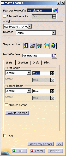
  2. Select Pocket.1 as the feature to modify.

    If you select several features, the field displays the number of selected elements. To act on this selection, just click the icon to display the Element list dialog box that allows you to:

    • view the selected elements
    • remove any element clicking the Remove button
    • replace any element using the Replace button and selecting a new one in the geometry or the specification tree.

    Shape Definition

  3. Remove features can have different shapes. The prism is the default shape. If you prefer a different shape, click any of the other three shapes available. To know how to create any of them, refer to the Prism, Sweep, Revolve, Thick Surface or External Shape tasks. For the purposes of our scenario, set the Sweep option .

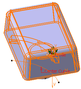
  4. Select Profile_sketch as the Profile/Surface defining the sweep.

  5. Select Center_Curve as the Center curve.
    Fillet

  6. Click the Fillet tab.

  7. Check the Lateral radius option and enter 1mm as the lateral radius value.

  8. Click Preview to check the operation.

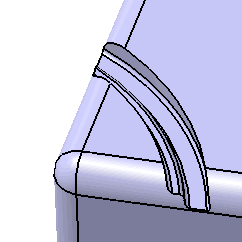
    The defined sweep has been removed from the shellable prism. Remove Sweep.X is added to the specification tree in the Solid Functional Set.X node.
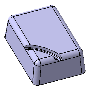
 

    Intersection Fillet

    The Intersection Fillet provides the capability to create fillets at the intersections with the targets. Also it provides the ability to keep the wall thickness constant when modifying wall creating feature that has set the constant wall option. In this case, the fillets are added at the intersections with the shellable prism.


  1. Select Intersection radius checkbox and enter 1mm.

  2. Click OK to confirm the operation.

  3. Wall

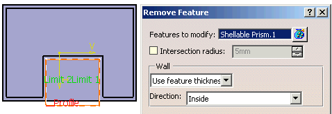
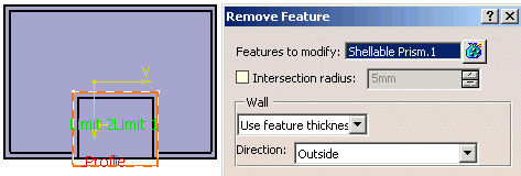
    You can control whether the wall is constructed inside or outside of the selected  profile. The default is an inside wall thickness.

    Inside is the inward direction of the target wall. It means that "inward" is relative to the solid shellable volume being modified such as the Shellable feature, not the modifying volume such as the Cut/Remove/Intersect feature.

    When the Wall direction is Inside, the wall will be constructed inward of the Shellable Prism.


    When the Wall direction is Outside, the wall will be constructed outward of the Shellable Prism.

     
  1. Click the Remove icon again to add another Remove feature.

  2. Select Pocket.1 as the feature to modify.

  3. Select RemoveSketch as Profile/Surface.

  4. Click Reverse Direction button.

  5. Enter 40mm for First length.

  6. Click OK.

  7. Remove Prism.X is added to the specification tree in the Solid Functional Set.X node.
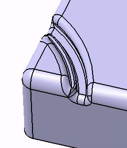
     
  8. Click Remove Prism.2 to edit the feature.

  9. Select Enter thickness for Wall Type and enter 0mm for Thickness.

  10.  
  11. Click OK.


Remove Command and Protected Volumes

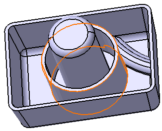
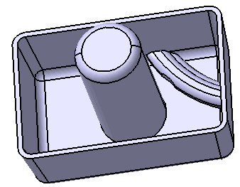
After you have generated a Remove feature from protected volumes, for example from a Cutout, material is generated as illustrated below:

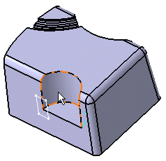
Cutout pointed by the cursor and sketch to be used for the remove operation
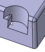
Remove operation accomplished on the cutout