This task shows you how to create a basic pad using a closed profile, the Dimension and Mirrored extent options.
-
Select Sketch.1 as the profile to be extruded.

-
Click Pad
 .
.
The Pad Definition dialog box appears and the application previews the pad to be created.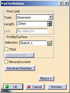

-
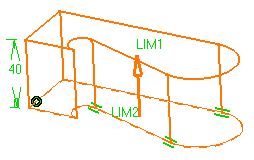
Enter 40 in the Length field to increase the length value.
 You
can increase or decrease length values by dragging LIM1 or
LIM2
manipulators.
You
can increase or decrease length values by dragging LIM1 or
LIM2
manipulators.The length value cannot exceed 1 000 000 mm.
-
Optionally, click Preview to see the result.
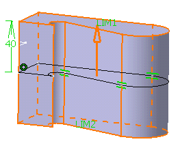
-
Click OK.
The pad is created. The specification tree indicates that it has been created.
About Profiles
When selecting a profile, keep in mind that:
-
You can use profiles sketched in the Sketcher or planar geometrical elements created in the Generative Shape Design workbench (except for lines).
-
You can also select diverse elements constituting a sketch. For more information, see Using the Sub-Elements of a Sketch.
-
If you click Pad
 with no profile previously
defined, just click the
 icon
available in the dialog box. You then just need to select a sketch plane
to enter the Sketcher and then create the desired profile.
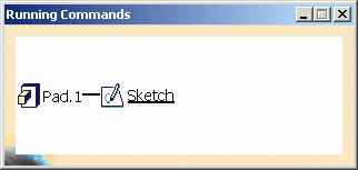
As soon as you click , the
Running Commands window displays to show you the
history of commands you have run. This informative window is particularly
useful when many commands have already been used, in complex scenarios
for example.
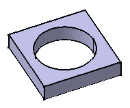
- Pads can also be created from sketches including several profiles.
These profiles must not intersect. In the following example, the sketch
to be extruded is defined by a square and a circle. Applying the Pad
command on this sketch lets you obtain a cavity:
You can select Generative Shape Design surfaces, non-planar faces and even CATIA V4 surfaces. For more information, refer to Creating Pads or Pockets from Surfaces.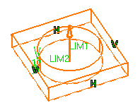
Preview

Result
- By default, if you extrude a profile, the application extrudes normal to the plane used to create the profile. To see how to change the extrusion direction, refer to Creating Pads not Normal to Sketch Plane.
- If you extrude a surface (for example created in the Generative Shape Design workbench), you need to select an element defining the direction because there is no default direction.
Changing Profiles
If you are not satisfied with the profile you selected, note that you can:
-
use any of these creation contextual commands available from the Selection field:
-
Create Sketch: launches the Sketcher after selecting any plane, and lets you sketch the profile you need as explained in the Sketcher User's Guide.
-
Create Join: joins surfaces or curves. See Joining Surfaces or Curves.
-
Create Extract: generates separate elements from non-connex sub-elements. See Extracting Geometry.
-
If you have chosen to work in a hybrid design environment, the geometrical elements created on the fly via the contextual commands mentioned above are aggregated into sketch-based features.

Limits
You will notice that by default, the application specifies the length of your pad (Type= Dimension option). But you can use the following options too:
- If you set the Up to Plane or
Up to Surface option, contextual commands creating new planes or
surfaces you may need are then available from the Limit field:
- Create Plane: see Creating Planes
- XY Plane: the XY plane of the current coordinate system origin (0,0,0) becomes the limit.
- YZ Plane: the YZ plane of the current coordinate system origin (0,0,0) becomes the limit.
- ZX Plane: the ZX plane of the current coordinate system origin (0,0,0) becomes the limit.
- Create Join: joins surfaces or curves. See Joining Surfaces or Curves.
- Create Extrapol: extrapolates surface boundaries. See Extrapolating Surfaces.
If you create any of these elements, the application then displays the corresponding icon in front of the field. Clicking this icon enables you to edit the element.
If you have chosen to work in a hybrid design environment, the elements created on the fly via the contextual commands mentioned above are aggregated into sketch-based features.
Options
The following pad creation options are available:
- Thick: adds thickness to both sides of your profile. To know how to use it, refer to Creating Thin Solids.
- Reverse side: applies for open profiles only. This option lets you choose which side of the profile is to be extruded. When designing thin solids, the option is meaningless.
- Mirrored extent: extrudes
the profile in the opposite direction using the same length value.
If you wish to define another length for this direction, you do not have to click the Mirrored extent button. Just click the More button and define the second limit.
A Few Notes About Pads
Keep in mind the following:
- Before clicking Pad, ensure that the profile to be used is not tangent with itself.
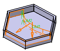
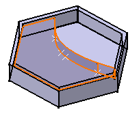
- The application allows you to create pads from open profiles
provided existing geometry can trim the pads. The pad below has been
created from an open profile which both endpoints were stretched onto
the inner vertical faces of the hexagon. The option used for Limit 1 is Up to
next. The inner bottom face of the hexagon then stops the
extrusion. Conversely, the Up to next option could not be used
for Limit2.
Preview
Result
However, if the application can generate an intersection between both profile endpoints, it produces a pad as in the following example. The profile chosen is an arc of circle. Although no existing geometry can trim the pad to be created, the application succeeds in generating a pad.
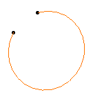
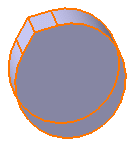
Profile
Result