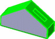
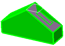
This task shows how to perform an extract from elements (curves, points, surfaces, solids, volumes and so forth).
This may be especially useful when a generated element is composed of several non-connex sub-elements. Using the extract capability you can generate separate elements from these sub-elements, without deleting the initial element.
Open the Extract1.CATPart document.
-
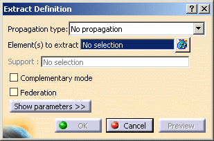
Click Extract
 .
. -
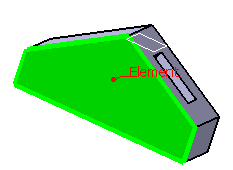
Select an edge or the face of an element.
The selected element is highlighted. 
Multi-selection is available to let you select several elements to be extracted. -
- Point continuity: the extracted element will not
have a hole.
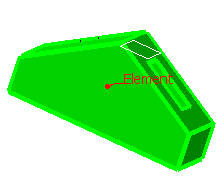
- Tangent continuity: the extracted element will be
created according to tangency conditions.

- Curvature continuity: the
extracted element (necessarily a curve) will be created according
to curvature conditions.
- No propagation: only the selected element will be
created.

- Point continuity: the extracted element will not
have a hole.
-
Click Show parameters>> to display further options. They are only valid for curves.

These options are only valid for curves. 
- Distance Threshold: specifies the distance value
between 0.001mm and 0.1 mm below which the elements are to be
extracted.

- The default value is 0.1mm, except if a Merging Distance
has been defined different from 0.001mm in Tools >
Options. In this case, the Distance Threshold value is
initialized with the Merging Distance value.
To have further information, refer to the General Settings chapter.
- It is available with all propagation types, except for the No propagation type.
- The default value is 0.1mm, except if a Merging Distance
has been defined different from 0.001mm in Tools >
Options. In this case, the Distance Threshold value is
initialized with the Merging Distance value.
- Angular Threshold: specify the angle value between 0.5 degree and 5 degree below which the elements are to be extracted (the default value is 0.5deg)
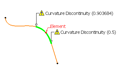
- Curvature Threshold: specifies a ratio between 0 and
1 which is defined as follows:
if ||Rho1-Rho2|| / max (||Rho2||,||Rho1||) < (1-r)/r
where Rho1 is the curvature vector on one side of the discontinuity, Rho2 the curvature vector on the other side, and r the ratio specified by the user;
then the discontinuity is smoothed.For example, r=1 corresponds to a continuous curvature and r=0.98 to the model tolerance (default value). A great discontinuity will require a low r to be taken into account.

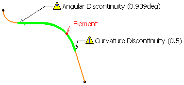
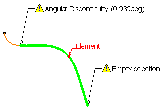
Curvature Threshold = 0.98 Curvature Threshold = 0.80 Curvature Threshold = 0.50 
To sum up: - when Point continuity is selected, only the Distance Threshold is activated
- when Tangent continuity is selected, both Distance and Angular Thresholds are activated
- when Curvature continuity is selected, all Thresholds are activated.
- Distance Threshold: specifies the distance value
between 0.001mm and 0.1 mm below which the elements are to be
extracted.
-
Click OK to extract the element.
The extracted element (identified as Extract.xxx) is added to the specification tree.
Additional Parameters
- Checking Complementary mode highlights and therefore selects the elements that were not previously selected, while deselecting the elements that were explicitly selected.
- Checking Federation generates groups of elements belonging to the resulting extracted element that will be detected together with the pointer when selecting one of its sub-elements. For further information, see Using the Federation Capability.
You can select a volume as the element to be extracted.
To do so, you can either:
select the volume in the specification tree, or
use the User Selection Filter toolbar and select the Volume Filter mode.
For further information, refer to the Selecting Using A Filter chapter in the CATIA Infrastructure User's Guide.In both cases, the result of the extraction is the same whatever the chosen propagation type.
- If you extract an internal edge that you want to propagate, and there is an ambiguity about the propagation side, a warning message is issued and you are prompted to select a support face. In this case, the dialog box dynamically updates and the Support field is automatically filled in.
In all other cases, you are advised to select a support element so that the orientation of the resulting extract feature remains the same even if the geometry is modified.
Creating Contextual Extracts
Here is an example with the Parallel Curve command when right-clicking the Curve field:
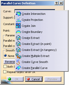
- If you select the Create Extract contextual command, the Extract Definition dialog box opens.
- If you select the Create Extract (in
point) or Create Extract (in tangency) contextual
command, no dialog box opens.
Both commands let you create extracts with a pre-defined propagation. You just need to select a sub-element such as wire edge, border edges, face, sub-elements of a volume or a solid. 
You cannot select edges as a support is needed. 
You need to leave the mouse on the pre-selected sub-element to preview and compute the propagation (in green): 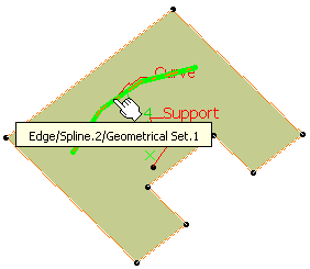
Editing Extracts
Miscellaneous
- In a .CATProduct document containing several
parts, you can use the extract capability in the current part from the
selection of an element in another part, provided the propagation type is
set to No Propagation.
In this case, a curve (respectively a surface or point) is created in the current part if the selected element is a curve (respectively a surface or point); the Extract parent therefore being the created curve (respectively the surface or point).
Note:- if another propagation type is selected, the extraction is impossible and an error message is issued.
- when editing the extract, you can change the propagation type providing the parent belongs to the current part.
- in the current part, if you select an element using the Tangent, Point or Curvature continuity as the propagation type, a warning is issued and you have to select No propagation instead.
- If the selected element is not tangent continuous and the propagation type is set to Tangent continuity, an error message is issued.
- If the selected element is a wire that is not curvature continuous and the propagation type is set to Curvature continuity, an error message is issued.
- If the selected element has a support face and is not a surface, even though the Complementary mode option is checked, the Complementary mode will not be taken into account for the extraction and the option will therefore be inactive. After the extraction, the option will be available again.
- If the selected element is a border edge, the propagation is done along the boundary of the support and does not take into account internal edges.
- When the result of an extract is not connex (during creation or edition) due to naming ambiguity, you can then select the part to keep to solve the ambiguity.
- If two elements have a same name and are distant of less than 0.1mm, the naming ambiguity mechanism fails and an error message is issued.
- You cannot copy/paste an extracted element from a document to another. If you wish to do so, you need to copy/paste the initial element first into the second document then perform the extraction.
- If there is several solutions for the propagation, the computation of the extract stops at the junction point.
![]()
