-
Select the circle as the profile to be extruded.
-
Click Pad
 .
.
The Pad Definition dialog box appears and the application previews a pad with a default dimension value. -
Click the arrow in the geometry area to reverse the extrusion direction (or click the Reverse Direction button).
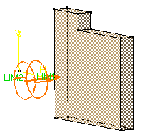
-
In the Type field, set the option to Up to next.
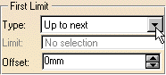
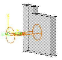
This option assumes an existing face can be used to trim the pad. The application previews the pad to be created. The already existing body trims the extrusion.
Optionally, click Preview to see the result.
-
Click OK.
The pad is created. The specification tree indicates this creation.
![]()