-
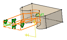
Select the profile to be extruded.

-
Click Pad
 .
.
The Pad Definition dialog box appears and the application previews a pad with a default dimension value. -
In the Type field, set the Type option to Up to surface.
-
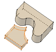
Select the vertical circular face. This face belongs to the same body as the existing pad.
Using the Up to surface option, you can select a face belonging to the same body as the sketch or a face belonging to Part Body.
The face trims the extrusion.
Contextual Commands
Contextual commands creating the surfaces you need are available from the Limit field:
- Create Join: joins surfaces or curves. See Joining Surfaces or Curves.
- Create Extrapol: extrapolates surface boundaries or curves. See Extrapolating Surfaces and Extrapolating Curves.
If you create any of these elements, the application then displays the join or the extrapol icon in front of the Limit field. Clicking this icon enables you to edit the element.
-
An Offset option is available in the dialog box. Enter -30 as the offset value. This offset is the distance between the surface and the top face of the pad to be created.

Optionally click Preview to see the result.
-
Click OK.
The pad is created. The specification tree indicates this creation.
![]()
- By default, the application extrudes normal to the plane used to create the profile. To see how to change the direction, refer to Pad not Normal to Sketch Plane .
- You cannot use the same surface to trim both limits of a pad, even if you define an offset value for one of the limits.