-
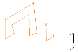
Select the profile to be extruded.

-
Click Pad
 .
.
The Pad Definition dialog box appears and the application previews a pad with 10 mm as the default dimension value. -
In the Type field, set the Type option to Up to plane.
-
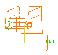
Select Plane.1.
The application previews the pad to be created. The plane trims the extrusion. An Offset option is now available.
Contextual commands creating the planes you need are available from the Limit field:
- Create Plane: see Creating Planes
- XY Plane: the XY plane of the current coordinate system origin (0,0,0) becomes the trimming element.
- YZ Plane: the YZ plane of the current coordinate system origin (0,0,0) becomes the trimming element.
- ZX Plane: the ZX plane of the current coordinate system origin (0,0,0) becomes the trimming element.
If you create any of these elements, the application then displays the plane icon in front of the Limit field. Clicking this icon enables you to edit the element.

-
Enter -20 as the offset value. This offset is the distance between the plane and the top face of the pad to be created.
Optionally click Preview to see the result. -
Click OK.
The pad is created. The specification tree indicates this creation.
![]()