-
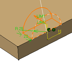
Select the profile you wish to extrude.

-
Click Pad
 .
.
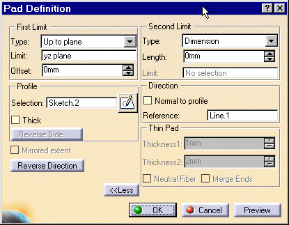
The Pad Definition dialog box appears and the application previews the pad to be created.
-
Set the Up to plane option and select plane yz. For more about this type of creation, refer to Creating Up to Plane Pads.
-
Click the More button to display the whole dialog box.
-
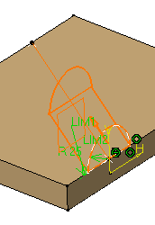
Uncheck the Normal to profile option and select the line as shown to use it as a reference.

The application previews the pad with the new creation direction.

Contextual commands creating the directions you need are available from the Reference field:
- Create Line: for more information, see Creating Lines
- Create Plane: see Creating Planes
- X Axis: the X axis of the current coordinate system origin (0,0,0) becomes the direction.
- Y Axis: the Y axis of the current coordinate system origin (0,0,0) becomes the direction.
- Z Axis: the Z axis of the current coordinate system origin (0,0,0) becomes the direction.
If you create any of these elements, the application then displays the line or the plane icon in front of the Reference. Clicking this icon enables you to edit the element.

-
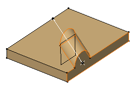
Click OK to confirm the creation.
The pad is created. The specification tree indicates this creation.