If a cell of the selected element relies on more than one support, you can choose the support you need.
Open the Multi-Supports1.CATPart document.
Creating a blend between a surface and a join
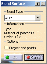
The Blend Surface dialog box appears.
-
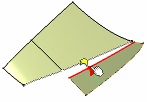
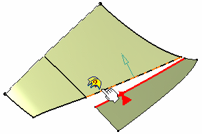
Move the pointer over the edge of a surface and click on it.
-
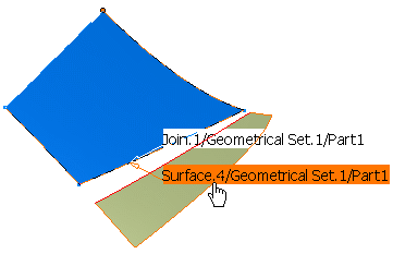
Move the pointer over the edge of the second surface and click on it.
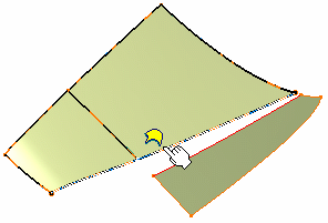
The information tag is displayed to inform you that only one surface can be selected for the blend operation.
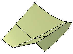
The blend surface is previewed.
-
Click Cancel in the Blend Surface dialog box.
-
Hide the Boundary.1 curve: right-click it in the specification tree and choose Hide/Show from the contextual menu.
-
Perform steps 1 and 2 again.
Move the pointer over the edge of the second surface.
An information tag
![]() is
displayed informing you that two or more surfaces can be selected.
is
displayed informing you that two or more surfaces can be selected.
-
Right-click the tag to display the number of solutions and choose which support to keep for the blend operation.
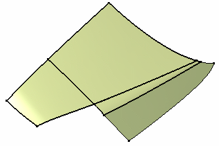
The blend surface is previewed.
-
Click OK in the Blend Surface dialog box to create the blend surface.
Creating a blend between two joined entities
-
Click the FreeStyle Blend Surface icon:

The Blend Surface dialog box appears.

-
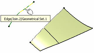
Move the pointer over a curve and click on it.
-
Move the pointer over the edge of a surface and click on it.
An information tag
![]() is displayed
informing you that only the selected surface only relies on one support.
is displayed
informing you that only the selected surface only relies on one support.
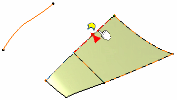
The blend surface is previewed.
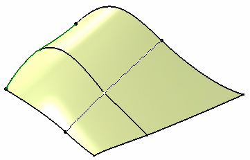
-
Click OK in the Blend Surface dialog box to create the blend surface.
The User Selection Filter toolbar is available with this functionality.

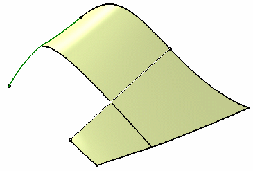
In the above example, had you deselected the Feature Element Filter mode, the Blend Surface would have been created between a surface and a 3D curve (and not between Join.1 and Join.2)
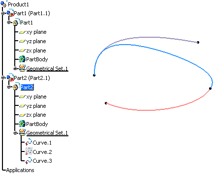
You can create a feature whose inputs belong to two different parts. An import in the current part is performed of the input belonging to the non current part: it is copied in the current part and put in no show. The feature is created in the current part as well.
Let's take an example with the Match Curve functionality.
-
Select the first curve to be matched.
-
Click the Match Curve icon:

-
Select the second to be matched.
-
Click OK.
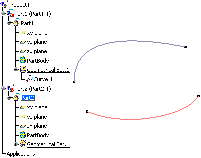
In the specification tree, the matched curve is created in the current part as well as the copied curve which is put in no show.
The Keep original option must be selected from the Dashboard.