This task explains how to create a blend surface between two pre-existing surfaces.
- two edges with the same number of faces
- one edge with only one face, the number of faces of the second edge is insignificant.
Open the FreeStyle_Part_42.CATPart document.
-
Click the FreeStyle Blend Surface icon:

The Blend Surface dialog box appears. 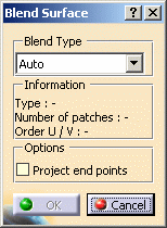

Three modes are available to create blend surfaces: - Analytic: when the selected surface edges are
isoparametric curves, the blend surface is computed in exact mode,
based on the selected surfaces control points.
Moreover, the blend surface presents a point, tangency and curvature continuity with the initial surfaces.
When in analytic mode and Tangency continuity, depending on the geometry configuration, twisted surfaces may be generated.
In this case, it is best to use the Proportional continuity, that allows the creation of the blended surface while taking the tangency continuity into account, then check the continuities if needed. - Approximated: regardless of the type of the selected surface edges, the blend surface is created according to an approximation between the initial surfaces.
- Auto: the system optimizes the computation mode, trying first to create the blend surface in Analytic mode, then, if not possible, in Approximated mode.

When in P1 mode, only the Auto mode is available. Information on the blend surface is displayed in the Blend Surface dialog box: - the blending type used (especially useful when working in Auto mode)
- the number of patches making up the surface
- the order of the blend surface along U and V
- Analytic: when the selected surface edges are
isoparametric curves, the blend surface is computed in exact mode,
-
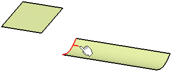
Move the pointer over one of the surfaces and click one of its edges.
You can select edges either from outside the surface (i.e. the pointer points towards the surface) or from within the surface (i.e. the pointer is over the surface when selecting the edge) 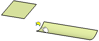
-
Click the edge of the second surface.
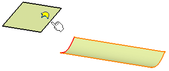
- The
 tag
informs you that there is only one surface to be selected.
 - In case the selected
edge relies on more than one support, the
 appears.
Please refer to Selecting a Support for further information.
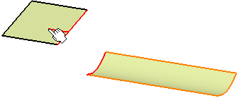
The blend surface is automatically previewed. - The
-
Right-click a limit point and choose one of the options from the contextual menu.
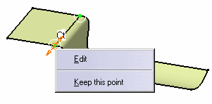
-
From the Dashboard, click on the Continuity icon
 and right-click onto the identifier to edit the continuity constraint on
the boundary of the blend surface and the selected surfaces, using the
contextual menu.
Change both continuities to Tangent.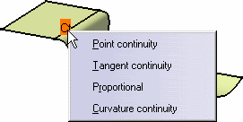
Available continuity types are: Point, Tangent, Proportional and Curvature. - Point: the surfaces share each point of their common boundary, i.e. there is no gap between the surfaces
- Tangent: the surfaces share a common tangent plane (i.e. normal) at each point of their connection
- Proportional: similarly to
the Tangent option, surfaces share a common tangent plane
(i.e. normal) at each point of their connection, but the longitudinal
variation from one point to the other is smoother, as the system
automatically re-distributes the control point location on the blend
surface
This mode is automatically set for both limits of the blend surface. - Curvature: the surfaces share a common curvature and tangent plane at each point of their connection
-
Still from the dashboard, click the Tensions icon:


The tension values are displayed on the element along with a green segment representing the direction and limits of the blend surface tangent at its middle-points. You can modify the tension values by sliding the green triangle along the direction. 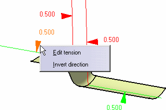
-
Right-click on the top boundary tension identifier and choose Invert direction.
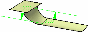
- In the case of an approximated blend type, you can modify the local
tangent and curvature parameters.
You can modify the tangency between the free edges and the edges of the support surface by clicking either Tangent or Normal. - If you move the coupling points onto the edges of the support surface, only the normal direction is kept for the free edges of the blend
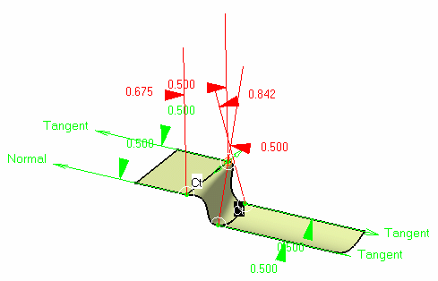
Tensions are now homogenized between blend surfaces and blend curves, so that the borders of a blend surface have the same shape as the blend curves, providing they are built on the same supports. 
This homogenization is only possible with an approximated blend surface. 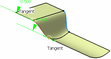
- In the case of an approximated blend type, you can modify the local
tangent and curvature parameters.
-
Invert the top tension to come back to the initial surface, click
 to deactivate the tensions, and click the Contact Points icon
 .
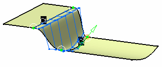
.Manipulators are displayed on the connection, allowing you to interactively define the blend limits by simply sliding them along the boundaries. 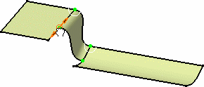
You can edit the contact points by right-clicking any of them to display the contextual menu and choosing the Edit item.
The Tuner dialog box opens to let you key in a new value, in percentage of the total boundary.
If you click on the Furtive Display icon  from the dashboard, control points of the created element are displayed.
-
Click OK in the Blend Surface dialog box to create the blend surface.
It remains selected, thus allowing to immediately analyze its connection to the other surfaces, for example. The Project end points option allows linear projection of the smaller edge, if selected first, onto the other surface as shown to the left. To the right is the resulting blend without the Project end points option. 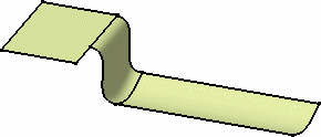
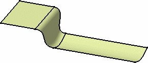

Should there be a twist between the two surfaces, the blend surface is not created. Modifying the continuity may enable the blend creation. 
Available capabilities from the Dashboard, and/or specified through the FreeStyle Settings, are: datum creation, continuity, contact points, tensions, and furtive display.