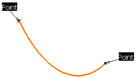
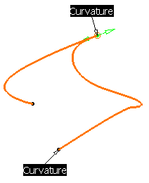
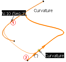
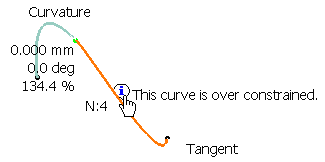
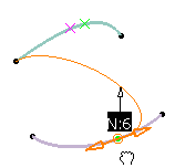
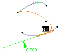
This task explains how to match a curve with another curve, a point on curve or a 3D point.
Open the FreeStyle_Part_44.CATPart document.
-
Select the curve you wish to match to another curve.
-
Click the Match Curve icon
 .
.
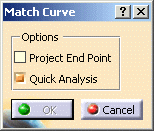
The Match Curve dialog box is displayed.
-
Select the second element (first reference element) for the match curve to be joined to. It can either be:
a curve
a point on curve with history
a datum point on curve
a 3D point
a vertex
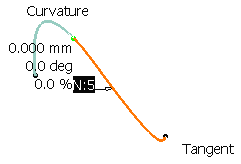
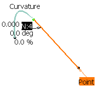
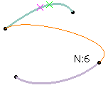
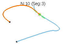
The number displayed on the first curve (Nx) corresponds to number of control points on that curve.
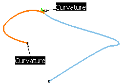
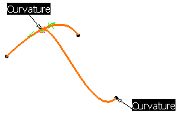
1. Match between a curve and another curve
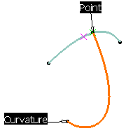
2. Match between a curve and a point on curve with history
3. Match between a curve and a datum point on curve
4. Match between a curve and a 3D point
5. Match between a curve and a vertex
- If you select a second reference element, both ends of the curve can be matched.
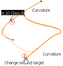
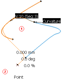
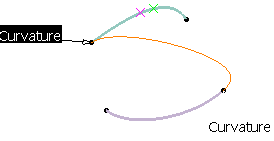
- If a curve is selected as the second element, all continuities can be applied (point, tangent, and curvature continuities)
- If a curve or a point on curve with history is selected as the second element, a point or curvature continuity can be applied.
- If a datum point on curve, a 3D point, a vertex is selected as the second element, a point continuity will be applied.
-
If the second element to match (a point on curve with history, or a vertex) lies one more than one support, the
 appears.
Refer to the Selecting a Support chapter for further information.
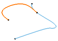
- The Project End Point option allows a linear projection of the minimum distance between two curves by projecting the initial curve onto the target curve.
- The Quick Analysis option enables to perform a violation
diagnosis of the curve matching. The original degree is kept (it is no
more automatically increased). Several parameters are taken into account
between the two curves:
- distance
- continuity degree
- curvature difference
-
Click OK in the Match Curve dialog box to create the matched curve as it is previewed.
- increase the number of control points by clicking the number (the value is increased by one) or by selecting a number from the contextual menu, or
- modify the continuity type by clicking it (it is displayed sequentially) or by selecting a type from the contextual menu.
Working with the FreeStyle Dashboard
-
Make sure the Continuity icon
 is active in the Dashboard and, right-click onto the identifier to edit
the continuity constraint, using the contextual menu.
You can choose from the point, tangency or curvature continuity type to be taken into account.
-
Make sure the U, V orders icon
 is active in the Dashboard so that the numbers of control points are
displayed.
-
Make sure the Contact Points icon
 is active in the Dashboard, to display the point manipulators and to move
the points along the curve, thus interactively redefining the connection
location.
-
Make sure the Tensions icon
 is active in the Dashboard, and modify the tension by sliding the
displayed value along the green segment.
This segment represents the direction and limits of the match curve tangent at its end-points.
-
Click OK in the Match Curve dialog box to create the matched curve as it is previewed.
-
When working in P2 mode, click the Break Surface or Curve icon
 and select the curve to be broken.
-
Select the side to be removed.
-
Click OK in the Break Options dialog box.
A new split curve is created replacing the initial one.
