- In P1 mode, the match operation does not modify the input surface, except if you modify its order.
- The Keep original option enables you to work on a copy of the input surface.
- When you select a frozen surface (a surface with an history) or a
non-Nurbs surface as input, a dialog box is issued warning you that an
automatic conversion will be automatically performed before the matching
operation:
- When an exact conversion is possible, a new Nurbs surface will replace the input one in order to perform the match. This new surface will be added in the specification tree.
- When there is a deviation or no exact conversion exists, the Converter Wizard panel appears allowing you to define the approximation according to a tolerance using parameters such as U, V orders, patch numbers, and deviation tolerance.
- Functionalities are available:
- through the FreeStyle Settings,
- from the Dashboard: temporary analysis, U, V Orders, keep original, auto detection, attenuation, continuity, contact points, and tensions.
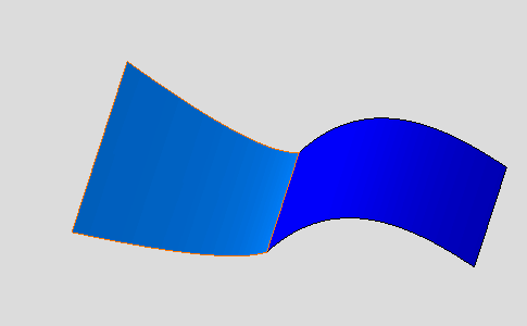
Open the FreeStyle_Part_41.CATPart document.
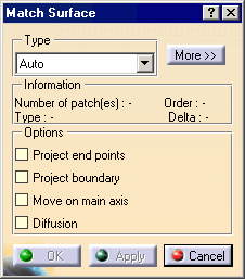
The Match Surface dialog box appears:
-
Click the More>> button in the Match Surface dialog box.
The Match Surface dialog box displays more information:
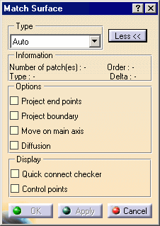
The Match Surface dialog box displays the following information:
-
Type:
-
Analytic: available only when the selected curve is an isoparametric curve. The match is computed based on a mathematical formula leading to an exact location of each of the selected curve control point.
Furthermore, if both selected curves present the same number of control points, the deviation is null. This option is P2-only. -
Approximated: regardless of the type of the selected surface edges, the match is based on the discretization of the selected elements, and is approximated accordingly. This option is P2-only.
-
Auto: the system optimizes the computation mode, trying first to create the match surface in Analytic mode, then, if not possible, in Approximated mode.
-
-
Information:
-
Number of patches: the number of patches making up the surface.
-
Type: the matching type used Analytic or Approximated (especially useful when working in Auto mode).
-
Order: the order of the surface to be matched.
-
Delta: the delta from the initial surface.
-
-
Options:
-
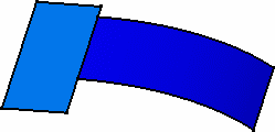
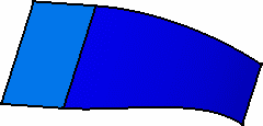
Project end points: this option makes linear projection of the smaller edge, when selected first, onto the smaller surface as shown to the left. This option is P2-only.
-
Project boundary: this option allows you to directly project the first selected boundary onto the second surface, by selection of the surface only. (You do not need to select a boundary on the target surface.) This option is P2-only.

-
Move on main axis: this option constrains the matched surface so that its control points can only be moved along the compass main axis. This option is only available with FreeStyle Optimizer. This option is P2-only.
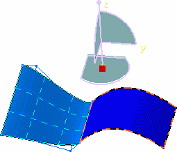 Unchecked
option.
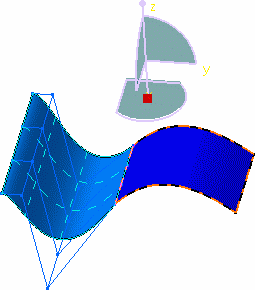 Checked
option.
 -
Diffusion: this option propagates evenly any modification performed using the control points.
-
-
Display:
-
Quick connect checker and orders: makes a quick connect checker and depending on the type of continuity connection, three values can be displayed:
-
Distance (mm): the maximum distance between the two elements.
-
Angle (degrees) between the tangents to the surfaces.
-
Curvature (%): that is the ratio between both surface curvatures.
-
-
Control Points: displays the control points and mesh lines on the initial surface, allowing you to dynamically modify them.
-
-
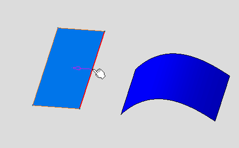
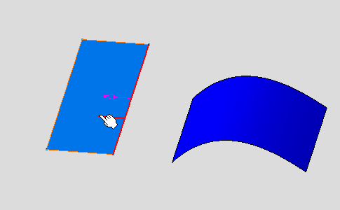
Move the pointer over one of the surfaces and click one of its edges.
You can select edges either from outside the surface (i.e. the pointer points towards the surface) or from within the surface (i.e. the pointer is over the surface when selecting the edge).
-
Move the pointer onto the second surface.
Possible boundaries for the match are highlighted as you move the pointer along.
-
Click the surface when the adequate boundary is highlighted.
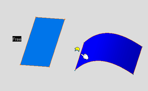
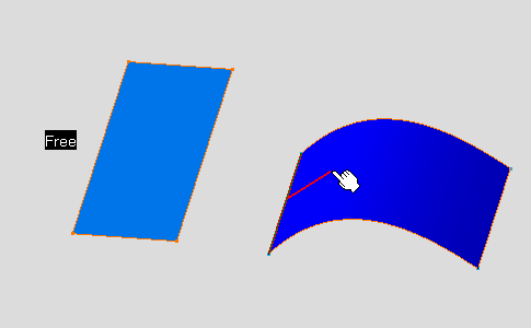
The
![]() tag informs you that there
is only one surface to be selected.
tag informs you that there
is only one surface to be selected.
In case the selected edge relies on
more than one support, the ![]() appears.
appears.
Please refer to Selecting a Support for
further information.
-
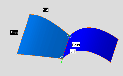
The match is automatically applied.
-
The first surface is recomputed so as to be connected to the second surface.
-
The continuity labels are displayed close to the matched surface (in the Dashboard, click on the Continuity icon
 if needed). When a continuity type leads to some inconsistencies, a
message is displayed on the surface, so that you can modify the
continuity type. Right-click them to change the continuity type from the
contextual menu.
Available continuity types are:-
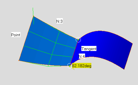
Point: the surfaces share each point of their common boundary, i.e. there is no gap between the surfaces.
-
Tangent: the surfaces share a common tangent plane (i.e. normal) at each point of their connection
-
Curvature: the surfaces share a common curvature and tangent plane at each point of their connection
-
Proportional: similarly to the Tangent option, surfaces share a common tangent plane (i.e. normal) at each point of their connection, but the longitudinal variation from one point to the other is smoother, as the system automatically re-distributes the control point location on the matched surface.
This mode is automatically set for both limits of the matched surface. -
Free: no constraint is imposed on the curve control points.
-
-
Manipulators are displayed on the connection (in the Dashboard, click on the Contact Points icon
 if needed), allowing you to interactively define the match limits by
simply sliding them along the target curve.
if needed), allowing you to interactively define the match limits by
simply sliding them along the target curve.-
You can edit the contact points by right-clicking to display the contextual menu and choosing the Edit item.
-
You can also use the Snap on Geometry option.
-
Functionalities are available from the contextual menu when right-clicking a contact point. These functionalities are P2-only.
-
-
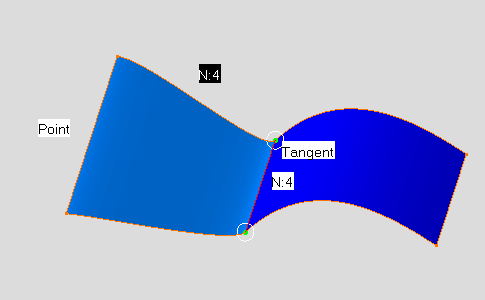
Set the continuity types to Point on the initial surface and Tangent on the target surface.
-
From the Dashboard, select the Tensions icon
 (P2-only).
-
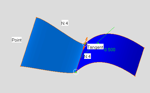
The tension values are displayed on the element along with a green segment representing the direction and limits of the match surface tangent at its middle-points. You can modify the tension values by sliding them along the direction.
-
You can right-click the tension value and select Edit tension from the contextual menu: enter a new value within the 0 to 1 range, using the Tension Tuner dialog box:

-
You can right-click the tension value and select Invert direction from the contextual menu to invert its direction.
-
Unselect the Tensions icon
 (P2-only).
-
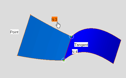
Change the surface order to 3 as shown.
-
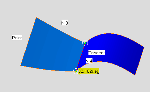
Select the Quick connect checker and orders option.
The quick connect checker displays the angle between the two surfaces.
-
Select the Control Points option. Click OK in the Control Points dialog box to recompute the match surface.
The Control Points dialog box appears.
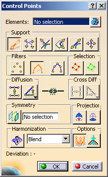
The control points and mesh lines are displayed on the initial surface. When a modification is not consistent with constraints previously set, as the choice of continuity for example, a message is displayed on the geometry. You then have the choice not to perform the modification, or to modify the constraint in order to edit freely the control points.
-
Click OK in the Match Surface dialog box.
