|
|
This task shows you how to display
continuities on elements and how to modify their values. Three other types of manipulators can be displayed on a given element, whether the selected or the resulting element: |
| These manipulators are displayed either by using the Dashboard (P2 only) as illustrated in this task, or by checking the adequate option in Tools > Options > Shape > FreeStyle. Once they are displayed, their behavior is identical regardless of the chosen interface style. | |
|
|
Open the FreeStyle_Part_41.CATPart document. |
|
|
|
|
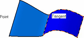
Texts indicating the continuity type wherever available are displayed. |
|
 |
|
|
|
 |
|
|
|
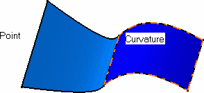
You can also simply click the text.
It will automatically change to the next type. |
|
The text changes to Curvature and the elements are updated in accordance. |
|
 |
|
|
|
In some cases the chosen type of
continuity is not compatible with the geometry or the modification. In that
case, a warning is displayed directly onto the geometry at the location
where the inconsistency arises. You can then change the continuity, or
modify the geometry itself. |
![]()