![]()
Using cutting planes, you can create sections, section slices, section boxes as well as 3D section cuts of your products automatically.
To take advantage of sectioning capabilities in a
CATAnalysis document, open the linked CATProduct before running the
sectioning command.
Section
Plane
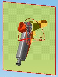
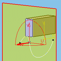
The section plane is created parallel to absolute coordinates Y, Z. The center of the plane is located at the center of the bounding sphere around the products in the selection you defined.
-
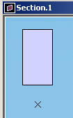
Line segments represent the intersection of the plane with all surfaces and volumes in the selection. By default, line segments are the same color as the products sectioned.
|
|
-
Points represent the intersection of the plane with any wireframe elements in the selection, and are visible in both the document window and the Section viewer.
|
|
|
Notes:
-
Any surfaces or wireframe elements in the same plane as the section plane are not visible.
-
If no selection is made before entering the command, the plane sections all products.
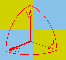
A plane has limits and its own local axis system. The letters U, V and W represent the axes. The W-axis is the normal vector of the plane.
|
|
You can customize settings to locate the center and orient the normal vector of the plane as well as de-activate the default setting taking wireframe elements into account.
This is done using the Tools > Options..., Digital Mockup > DMU Space Analysis command (DMU Sectioning tab).
Manipulating the Plane
Sectioning is dynamic (moving the plane gives immediate results). You can manipulate the cutting plane in a variety of ways:
-
Position it with respect to a geometrical target, by selecting points and/or lines
-
Change its current position, move and rotate it using the Edit Position and Dimensions command.
Section Results

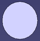
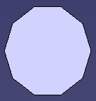
Results differ depending on the sag value used.
|
Using default value (0.2mm): |
Using a higher value: |
|
|
|
Sag: corresponds to the fixed sag value for calculating tessellation on objects (3D fixed accuracy) set in the Performance tab of Tools > Options > General > Display.
![]() By default, this value is set to 0.2 mm.
By default, this value is set to 0.2 mm.
In Visualization mode, you can dynamically change the sag value for
selected objects using the Tools > Modify SAG command.
Sectioning and 3D XML format
3D XML format is supported, which means you can:
-
open and/or insert a 3D XML document containing sections.
-
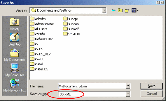
save as in 3D XML format a CATProduct containing sections.
-
customize 3D XML settings refer to the Customizing section of DMU Space Analysis User's Guide
 |
Notes:
-
The selected objects that are cut are not retrieved when exporting the sectioning results to 3DXML format
-
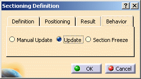
The behavior parameter (See the Sectioning Definition dialog box below) is not stored in the 3DXML file.
-
The information related to the grid (activate, values, behavior) is not retrieved
-
The applicative data under a section are not exported in 3D XML. This means that measures, distances, 3D annotations and 2D annotations are not exported if they are stored under the section.
3D Section Cut
3D section cuts cut away the material from the cutting plane to expose the cavity within the product, beyond the slice or outside the box.
P1 and P2 Capabilities
In DMU-P1, you cannot select products to be sectioned: the plane sections all products.
Creating Groups of Products
In DMU-P2, prior to creating your section plane, you can
create a group containing the product(s) of interest using Group
![]() in the DMU Space Analysis toolbar or Insert > Group... in the
menu bar.
in the DMU Space Analysis toolbar or Insert > Group... in the
menu bar.
Groups created are identified in the specification tree and can be selected from there for sectioning. Only one group per selection can be defined.
Creating section slices and section boxes are DMU-P2 functionalities.
Customization Recommendations
For performance gain purposes, when dealing with CATProducts containing a large amount of sections, it is strongly recommended to apply the following procedure before opening your CATProduct documents:
-
Select Tools > Options > Digital Mockup > DMU Navigator tab.
-
In Update settings category clear Update on product structure modifications and scenes activation option.

-
Click Ok when done.

Note that clearing the Update on product structure modifications and scenes activation option makes the three options available in Behavior tab of Sectioning dialog box ineffective (the sections will not be updated) as long as you product is opened in session.

For more information refer to:
-
Customizing section.
![]()
