|
|
Details about Inertia Measurements:
You can measure the 3D inertia
properties of both surfaces and volumes, as well as retrieve the density or
surface density if valuated from V4 model type documents. You can also
retrieve inertia equivalents set in
Knowledgeware formulas.
-
The area, density, mass and volume (volumes only) of the
object are calculated
-
The center of gravity G is expressed in the global
axis system, it is not possible to express this value in the local
axis system.
-
When there is no material applied to the selected
items, the center of gravity corresponds to a geometrical center of
gravity. In this case, it is recommended to use the
Measure item  tool
where it is possible to select a secondary axis system. Thus the
center of gravity coordinates will be expressed in this secondary
axis system. tool
where it is possible to select a secondary axis system. Thus the
center of gravity coordinates will be expressed in this secondary
axis system.
|
 |
-
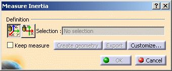
Click Measure Inertia
 .
In DMU, you can also select Analyze > Measure Inertia from the
menu bar. The Measure Inertia dialog box appears. .
In DMU, you can also select Analyze > Measure Inertia from the
menu bar. The Measure Inertia dialog box appears.
|
 |
|
 By default, 3D inertia properties are measured.
 |
|
The Measure 2D
Inertia icon lets you measure 2D inertia properties of plane
surfaces. |
Dialog box options
-
A Keep Measure option in the
dialog box lets you keep current and subsequent measures as
features in the specification tree. Some measures kept as features
are associative and
can be used as parameters.
-
A Create
Geometry option lets you create the center of gravity and the
axis system for principal axes in a part from inertia results.
-
An Export
option lets you write results to a text file.
-
A Customize... option
lets you define what will be computed and displayed in the dialog
box.
|
|
 |
In the Drafting workbench, the Keep Measure option is
not available. Measures are done on-the-fly. They are not persistent.
This means that they are not associative and cannot be used as
parameters. |
Note:
When you move the cursor over the geometry or specification
tree, its appearance changes to reflect the measure command you are
in  |
-
Click to select the desired item in the specification
tree, for example Valve.
 |
Selecting Items
|
In the geometry area, you can select
individual faces and edges on cgr files and in Visualization mode.
To...
|
Then
|
|
make a multiple selection |
Shift-click in the specification tree |
|
add other items to the initial selection |
Ctrl-click in the geometry area or the
specification tree |
|
select items using the bounding outline |
Drag (using the left mouse button) |
|
make your multiple selection.(P2 only) |
Use the Group command |
|
 |
Notes:
- Only items of the same type can be included in a multiple
selection or a bounding outline; you cannot mix volumes and
surfaces.
- Inertia measures made on a multiple selection of items are
not associative.
|
Dialog Box
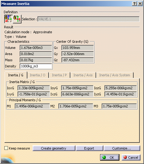
The Dialog Box expands to display the results for the
selected item.
The measure is made on the selection, geometry,
assembly or part. To measure the inertia of individual sub-products
making up an assembly and see the results in the document window, you
must select the desired sub-product.
In our example, the item selected has no sub-products. |
|
 |
|
The dialog box identifies the selected item and
indicates whether the calculation is exact or approximate:
-
In Design mode, measures (bounding box excluded) access exact data and
wherever possible true values are given. Note that it is possible
to obtain an exact measure for most items in design mode.
-
In Visualization mode, measures are made on
tessellated items and approximate values are given.
In addition to the center of gravity G, the principal
moments of inertia M and the
matrix of inertia calculated with respect to the center of
gravity, the dialog box also gives the area, volume (volumes only),
density and mass of the selected item.
You can also compute and display the
principal axes A. To do so,
you must first activate the appropriate option in the
Measure Inertia Customization dialog box.
The density is that of the material, if any, applied
to a product, part or part body:
-
If no density is found, a default value (1000 kg/m3
for volumes and 10 kg/m2 for surfaces) is displayed.
You can, if desired, edit this value to re-calculate all the other
inertia values and display them in the dialog box. Note:
re-calculated inertia values are not stored in the measure feature.
-
If sub-products or part bodies have different
densities, the wording Not uniform is displayed.
|
|
 |
To make sure, you retrieve the density on any
possible selection (surface and / or volume), you must select the
item (part or part body) in the specification tree and not in the
geometry area. |
|
 |
Notes:
- The bounding box calculation accuracy depends on the
one used for tessellation (SAG) on objects. This is set in the
Performances
tab page in Tools > Options
> General > Display.
By
default, this value is set to 0.2 mm.
-
You can access the density of parts saved as CGR
files and opened in visualization mode. This functionality is
available in both a part and a product context.
-
To do so:
-
Select the Save density in cgr option in the Cgr
Management tab (Tools > Options > Infrastructure > Product
Structure).
-
Open a part to which material has been applied
and save as CGR type.
The density is stored in the CGR file.
Important: The material must be applied to the part node. If
materials are applied to part bodies, no density is saved.
-
Close the Part document.
-
Open the CGR file or switch to DMU Space Analysis
and insert the part saved as CGR, then measure the inertia.
-
You must be in design mode to access the density of
part bodies to which materials have been applied.
-
Unless specified otherwise, material inheritance is
taken into account.
-
Density is a measure of an item's mass per unit
volume expressed in kg/m3; surface density is a measure of an
item's mass per unit area expressed in kg/m2.
|
|

|
|
 |
|
 |
The number of decimal places, the display of trailing
zeros and limits for exponential notation is controlled by the Units
tab in the Options dialog box (Tools > Options,
General > Parameters and Measure).
Elements placed in No Show are taken into account in
measure operation. |
Geometry area
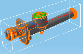
In the Geometry Area, axes of inertia are highlighted
and a bounding box parallel to the axes and bounding the selected
item also appears.
Color coding of axes:
-
Red: axis corresponding to the first
moment M1
-
Green: axis corresponding to the second
moment M2
-
Blue: axis corresponding to third moment
M3.
|
|

|
-
Click Customize... to
customize the inertia computation and define what will be
exported to the text file.
-
Click OK when done.
-
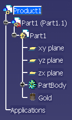
If you checked the Keep Measure option in the Measure
Inertia dialog box, your measures are kept as features and your
specification tree will look something like this.
|