![]()
Insert or open the
InertiaVolume.CATPart from the common functionalities sample folder
cfysm/samples.
-
Select Measure Inertia
 .
. -
Click Customize... in the Measure Inertia dialog box. The Measure Inertia Customization dialog box opens
-
In the Measure Inertia Customization dialog box, Select Inertia matrix / Axis System check box.
-
Click Apply. The Inertia / Axis System tab in the Measure Inertia dialog box becomes available.
-
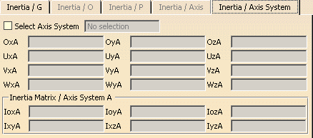
Click the Inertia / Axis System tab.
-
Select the Select Axis system check box.

-
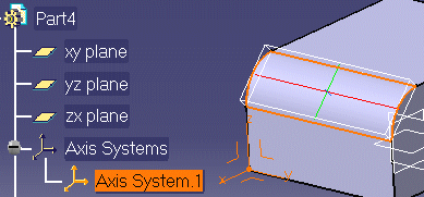
Select an axis system in the specification tree:

Note: You must select the axis system in the specification tree.

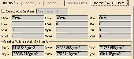
The name of the axis system as well as the origin O, (U, V, W) -vectors and the matrix of inertia with respect to the axis system are given in the dialog box. Entries for the matrix of inertia appear in the specification tree.


Note: Only axis systems created in the Part Design workbench (Axis System command accessible in the Tools toolbar) are valid.
-
Selecting another item measures inertia properties of the selected item with respect to the same axis system.
To change axis system, click the Select Axis System check box again, then select another axis system.
If you checked the Keep Measure option in the Measure Inertia dialog box, your matrix of inertia measures are kept as features and, if made with respect to a V5 axis system, are associative.
![]()