 |
Associativity
In a CATProduct, the geometry you create can be either
associative or non associative with the measure. If you want to create
associative geometry, check the Keep link with selected object option in
Tools > Options > Infrastructure > Part Infrastructure,
General tab
CATPart
In a CATPart, the geometry you create is associative.
 |
Note: In both cases, associative geometry can only be
created if your measure is
associative. |
|
 |
In the Drafting and Advanced Meshing
Tools workbenches, measures are done on-the-fly and are
therefore not persistent nor associative and cannot be used as
parameters.
|
|
 |
-
Make your measure using the appropriate measure command
(Measure between or Measure item)
|
The Create
Geometry button becomes available in the
Measure dialog box (except if we measure a point using
Measure item). . |
|
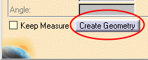 |
-
Click Create Geometry and follow
instructions depending on whether you are in a product or part:
If you are in a...
|
Then...
|
|
Product |
the Geometry Creation dialog box appears letting
you choose where you want the geometry created.
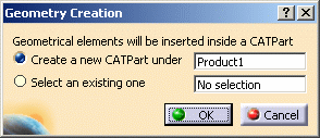
Select one of the two options below, then click
OK:
-
A new CATPart
In which case a CATPart is inserted under the active product.
-
An existing CATPart
In which case, click the option and select the CATPart in the
specification tree.
|
|
Part |
the geometry is automatically created in a new
geometrical set. |
|
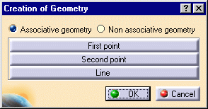
The Creation of Geometry dialog box
appears. |
|
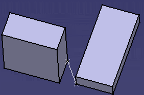
The example below shows the dialog box for a
measure made using the Measure Between command.
 |
-
Are you in a product?
|
|
|
Notes:
-
In a part, the geometry you create is
associative.
-
In both a product and a part, associative
geometry can only be created if your measure is
associative.
-
If Associative geometry is selected, the Keep
Measure option is checked to ensure that the geometry created
is based on measure results.
|
-
Select options in the Creation of Geometry
dialog box to create geometry desired.
If you made your measure using...
|
Then you can create...
|
|
Measure Between |
First point Second point
These are the two points between which the minimum distance is
measured
Line: the line representing the minimum distance result. |
|
Measure Item |
Center of gravity |
|
Measure Inertia |
Center of gravity
Axis system (for the principal axes). |
-
Click OK in the Creation of Geometry
dialog box when done.
|
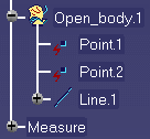
Geometry is created in the geometry area and is
added to the specification tree under the Geometrical set of a
new or an existing part. |
|
In the Measure Between example below, created
geometry is non-associative. This is identified by the red symbol
accompanying the point entry in the tree. |
|
 |
 |
-
Click OK in the Measure dialog
box when done.
|