This task shows you how to create and trim a BiW Welding Curve Bead.
- a joint and a joint body are already created: click the desired icon and select the joint body in the selection tree.
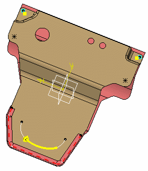
- a joint and a joint body are already created: select the joint body in the selection tree and click the desired icon (here is the example used for our scenario).
- no joint body is created. Select the components or the publications, and click the desired icon: a joint and a joint body are created if needed.
Open the ABF_CurveBead.CATProduct document.
Make sure the curve bead Fastener Type is set up in the standard file.
-
Select the joint body in the specification tree.
-
Click BiW Welding CurveBead
 in the Welding toolbar.
The BiW CurveBead Fastener Definition dialog box opens. -
Specify whether you wish to use the existing standard or not.
If a standard has been imported, a curve bead is created using this standard. If not, you are able to define your own values for each attribute. 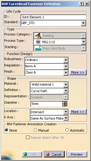

If the last location method is different from Explicit, the ABF application creates a specification part associated to the assembly joint if this specification part does not already exist. 
You must not delete this specification part. -
Define the functional parameters of the curve bead:
-
Robustness
-
Regulation
-
Finish
-
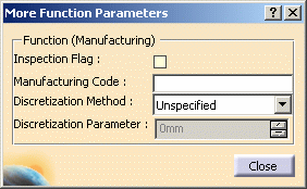
More>>: allows you to define Manufacturing parameters.
-
-
Unspecified: no discretization method is used. The default visualization is set in Tools > Options > General > Display > Performances > 3D Accuracy.
-
Sag: segments are defined on the curve according to the tolerance value set in the discretization parameter.
-
Step: equidistant points are created on the curve according to the value set in the discretization parameter.
-
Discretization Parameter: distance value for each curve bead depending on the chosen discretization method.
-
distance = sag if the sag discretization method was chosen
-
distance = step if the step discretization method was chosen
-
-
Both parameters will be used for the visualization of the curve bead and for the export/report. -
-
-
curve path
-
cylinder path
-
half cylinder path, etc.
-
-
Define the diameter in the following cases:
- Curve Path
- Cylinder Pipe
- Half Cylinder Pipe
Curve Path 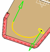
Cylinder 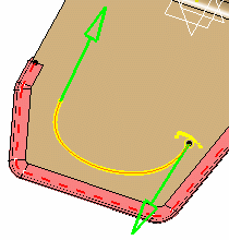
Half Cylinder -
Define the base and height in the following cases:
- Diamond Pipe
- Half Diamond Pipe
- Rectangle Pipe
- Half Rectangle Pipe
Diamond Pipe 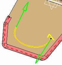
Half Diamond Pipe 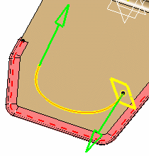
Rectangle Pipe 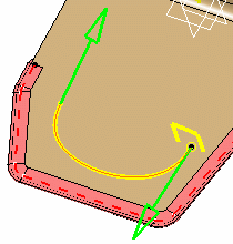
Half Rectangle Pipe -
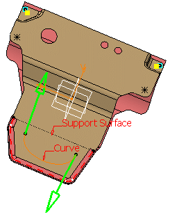
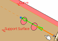
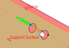
Select the location (see below):
According to the location you choose, different dialog boxes open, except when selecting the Explicit mode. -
Define the orientation of the curve bead by setting the K axis to either:
-
Same as Surface Material
-
Opposite to Surface Material
To visualize the K axis, the K Axis Only option should be checked in Tools > Options. -
-
Click OK to create the curve bead.
The curve bead (identified as Joint Element.xxx) is added to the specification tree, under the Assembly Joint Body node.
|
|
|||||||||||||||||||
Locating the CurveBead |
|||||||||||||||||||
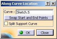
Along Curve |
|||||||||||||||||||
|
|||||||||||||||||||
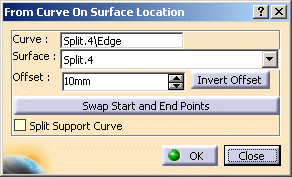
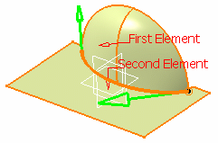
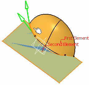
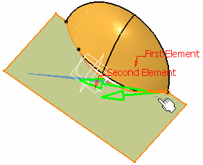
From Curve On Surface |
|||||||||||||||||||
|
|||||||||||||||||||
Intersect |
|||||||||||||||||||
| Open the Intersect1.CATProduct document. | |||||||||||||||||||
|
|||||||||||||||||||
Explicit |
|||||||||||||||||||
|
|||||||||||||||||||
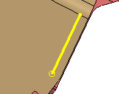

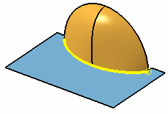
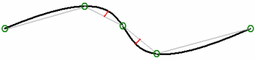
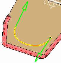
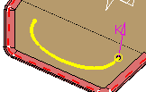
Trimming a Curvebead
-
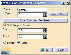
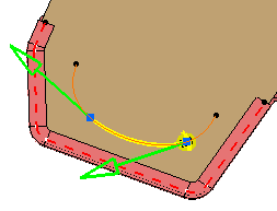
Select the curvebead location. In our scenario, we selected the From Curve On Surface location.
-
Check Split Support Curve.
- This option is only available with all the location methods but the Explicit location method.
- This option must be activated to be able to define the Start and End points values.
The Repeat object after OK button appears in the BiW CurveBead Fastener Definition. Refer to the Repeating CurveBeads to create more curve beads using the currently created spot point as reference. The From Curve On Surface Location dialog box opens. -
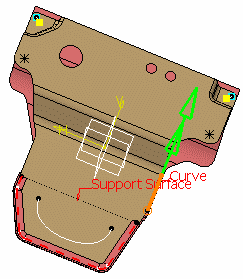
Enter 0.2 for the Start point.
-
Enter 0.7 for the End point.
-
Click Preview in the BiW CurveBead Fastener Definition dialog box to preview the curve bead.
-
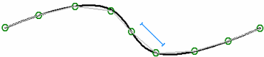
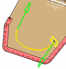
Check Swap Start and End Points.
The Start and End point coordinates are automatically recalculated and new values are displayed within the dialog box, but the curve bead position within the geometry does not change. 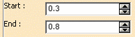
The curvebead is modified with its start and end points recalculated. 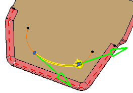
-
Click OK to create the trimmed curve bead.
Note that:
- the selection of the curve must be done within the sub-components of the curve bead's reference product, except when for the Explicit location method.
- When selecting the curve (except for the Explicit location method), it is recommended to select published elements in order to guaranty associativity between elements.
- to authorize the selection of only published elements, check the following option using Tools > Options > Infrastructure > Part Infrastructure > General > Only use published elements for external selection keeping links.
- when the On Support Surface and Explicit methods are activated, the application will ignore the active Part Infrastructure setting Only use published elements for external selection and will enable the usage of non published external geometry.
![]()