 |
-
Select the objects for which you wish to generate a
report. The object and the parent of higher level are selected.
| You can select them either in the specification
tree or in the 3D geometry. |
 |
You can modify the selection
once in the command. |
-
Click BiW reporting  from the BiW Fasteners Report sub-toolbar.
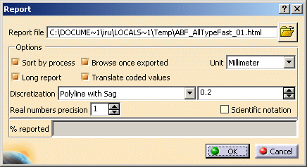
| The Report dialog box opens. |
The directory for the report file is the one defined in
Customizing General Settings.
You can modify the path by clicking the Browse icon. The
Report
file dialog box displays letting you choose the file. |
 |
| The dialog box enables you to customize the report through
several options:
|
-
Click OK.
| The progress bar shows you the remaining exported
percentage. |
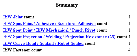
| The CATIA BiW Fasteners report opens. It displays: |
- General information:
- the date
- the product name
- the unit
- a summary containing (number of features) fasteners sorted by
process type and process category.
 |
 |
Fasteners belonging to a
same process type or process category are displayed in the
same order as they appear in the specification tree. |
|
| The following tables are contained into domains: |
- Joint attributes
- joined components
- Part path ID, Part Number, Version, Material
- joint bodies
- BiW Body Name, Stacking, Thicknesses Count, Zone ID,
Layer number for each joined contact
zone, etc.
- BiW Fasteners sorted by process type and process category (if
option checked)
- general attributes: BiW Joint and Joint Body Names, Process
Category, K Flag, I Flag, Layer number, X, Y, Z coordinates of
the fastener's reference tangent vector (U), etc.
- projection attributes (only in long reports): Zone path ID,
Normal and projection point coordinates, Material, Thicknesses
Values and order of the projection
attributes depend on the thickness crossing computation. For
further information, refer to the
Ordering Thickness Crossing Criteria chapter.
- Projection fasteners attributes (only in long reports)
- Curvilinear fasteners discretization attributes (only in long
reports)
- Point Count, for each point the localization coordinates
(X, Y, Z), the reference normal (W) and the tangent vector (U).
|
 |
| |
 |
- You can only report BiW objects.
- A warning message
is diaplayed in case errors occur during the report process. They
are logged in a .xml file.
Refer to the Import
chapter for more information.
- One single log file is issued per structural report.
- Deactivated features are not reported;
they appear in the log file.
- If no object is selected, all the active BiW objects as well
as the sub-products are reported.
- The products coordinates are reported relatively to the
active product coordinates.
- The header always displays the active product information
even if the report is for an assembly.
- When you have just created a feature, the latter is taken
into account when clicking the BiW reporting icon. Expand the
specification tree to ensure you selected the correct objects.
|
|