 |
-
Click Automotive BiW Fastening data export  in
the
Automotive BiW Fasteners
toolbar.
|
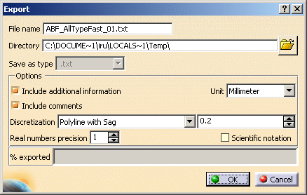
The Export dialog box opens.
It shows:
|
| You can modify the path by clicking the Browse icon.
The Select directory dialog box opens letting you choose the file. |
 |
| The dialog box enables you to customize
the neutral file through several options: |
- Include additional information: the neutral file
will start with the commented header block showing keywords
description.
- Include comments: glossary at the beginning of the
neutral file
- Unit: either millimeter or inch
- Discretization:
- Polyline with sag: segments are defined
on the curve.
- Polyline with step: equidistant
points are created on the curve.
 |
 |
The maximum sag and step
values either are read on the curvebead if a
curvebead's
Discretization Method is defined or correspond to the
value associated to the discretization in the Export dialog
box. |
- Numerical value: for discretization, the value should be between 0.01 and 10 mm (depending on the chosen
unit).
- Real numbers precision: number of decimal digits
of all the real numbers written in the neutral file and of the
discretization values displayed in the dialog box above.
This number is comprised between 0 and 10.
- Scientific notation: it will be used in the neutral
file (power of 10)
|
-
Select one or
more elements in the reference product to be included in the export
file. They can be:
-
joints:
the selected joint and all its children (joint bodies and joint
elements if any) are highlighted in the specification tree
-
joint
bodies: the selected joint body, its parent and children (joint
and joint elements if any) are highlighted in the specification
tree
-
joint
elements: the selected joint elements and its parent (joint and
joint body) are highlighted in the specification tree
|
 |
You can also select several
elements from two sub-products. In this case, the File name field
is grayed out. As many export files are created as there are
sub-products. The name of each export file corresponds to the name
of the sub-product.
If no element is selected, the export applies to the whole active
product. |
-
Click OK.
| The progress bar shows you the remaining exported percentage.
|
-
Open the file as per the path indicated. Its name is
the same as the reference products. You may change it if you wish.
The format is tab separated text, allowing to open it in a
spreadsheet application.
The structure of the document is the following: |
- Comments
- Header
- Joined parts attributes
- Path ID, JCPN, ZMATNAM, etc.
- Joint attributes
- Joint part
- Joint body attributes
- Zone attributes (ZNAM, Layer,
etc.)
- Joint element attributes (ID, Process Category, Process
Type, Layer, K Flag, IF Flag, Reference Normal (W) and
Tangent Vector (U) coordinates, etc.)
- Curvilinear fasteners discretization attributes, in
order: Point Count, location coordinates (LOCX, LOCY, LOCZ)
on each discretization point, W Normal Vector Coordinates (WX,
WY, WZ) on each discretization point, and U Tangent Vector
coordinates (UX, UY, UZ) on each discretization point.
- Projection fasteners attributes (ID, Projection Zone)
- INFO attributes (only in long reports: Zone Path ID,
Normal and projection point coordinates)
Values and order of the projection info
attributes depend on the thickness crossing computation. For
further information, refer to the
Ordering Thickness Crossing Criteria chapter.
- INFO1 attribute (Length, Volume)
|
| One neutral file associated to the reference product is
created. If the selected features belong to different products,
there will be as many export files as there are different products. |
 |
|