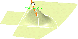
In this task you will learn how to fill the space between three surfaces.
You can fill the space between three or more elements (up to nine). The elements can be either curves or any surface type element. These elements must be contiguous in only one point.
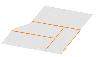
Open the Fill1.CATPart document.
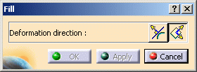
The Fill dialog box is displayed allowing you to define the Deformation direction.
This will let you deform the resulting filling surfaces according to the Compass Direction or Normal to the Surface Direction.
-
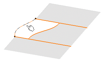
Select the boundary of the first surface.
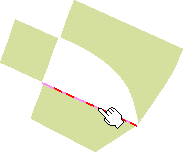
-
Select the boundary of an adjacent surface.
-
Select the boundary of all other surfaces, still going from one surface to its direct neighbor.
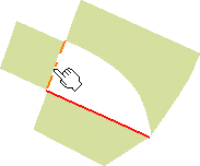
Once you have selected the last boundary contiguous to the first selected surface, the filling surfaces are created.
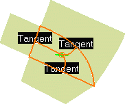
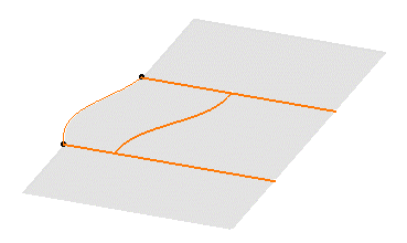
If you checked the Continuities option from the Dashboard (P2) or the FreeStyle Settings, the corresponding information is displayed on the surfaces:
-
Right-click the displayed text to edit the continuities.
You can choose from Point or Tangent continuity, depending on the geometry configuration. Tangent continuity is available only when filling a closed contour.
-
Use the manipulators at the center point (P2 only) to deform the generated surfaces. The deformation depends on the chosen icon: Normal to the Surface Direction, or according to the Compass Direction.
While deforming, set continuities are retained.
Capabilities are available from the contextual menu when right-clicking the manipulator.
The center point is not displayed if only one filling surface is created or when four filling surfaces are generated.
-
Click OK to create the filling surfaces.
-
You can use the graphic properties to modify the colors of the filling surfaces to better identify them. To this end, select each surface either in the geometry or in the specification tree, and call the Properties dialog box; Graphic tab, and modify the Fill color.
-
You can fill the space between different types of elements. For example, select a curve, two surfaces supporting a blend surface and the blend itself. In this case, the intersections between the selected edges on the surfaces and the blend limits are automatically detected, and the filling surface created accordingly.
Furthermore, only the Point continuity is available on the curve.
Similarly, you can fill three or more open-sided contours when composed of surface boundaries only. A temporary blend curve is created to close the contour when you click Apply, allowing the system to compute the filling surfaces.
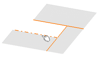
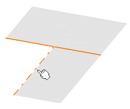
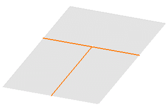
You can also fill the space between two intersecting curves, or surfaces, forming an open angle. To do this, simply select these curves or surface boundaries, then click Apply in the Fill dialog box. The system automatically creates temporary curves matching the selected ones to close a contour before filling it.
-
Make sure you select contiguous surface boundaries, especially when filling the space between more than three surfaces. Do not select boundaries randomly.
-
If four edges have been selected, a mono-patch surface is created. However, if three, five or more edges (up to nine) have been selected, as many surfaces are created as selected edges.
-
A gap between two selected boundaries, that exceeds the set tolerance (0.01 mm) is identified for correction purposes. A text is displayed, indicating the gap value, and the fill cannot be performed.
If the gap is smaller than 0.01 mm, the fill is automatically performed complying with the tolerance all around the selected edges.
-
Available capabilities from the Dashboard, and/or specified through the FreeStyle Settings, are: datum creation, temporary analysis, auto detection (Snap On Edge option only), attenuation, continuities and furtive display.