You should be familiar with the following basic methodological approach and concepts:
Mesh Part / Mesh / Mesher
A mesh part is a mesh specification, composed of elements
and nodes. You can define a
mesh part by setting global parameters and local specifications.
A mesh part is updated when it is completely meshed.
A mesh is the result of a mesh part (generated using global parameters stored in the mesh part).
Some meshers work directly on the geometry (for example the OCTREE meshers). Others work with a simplified geometry: this can improve performance and mesh quality.
Specification Tree Symbols
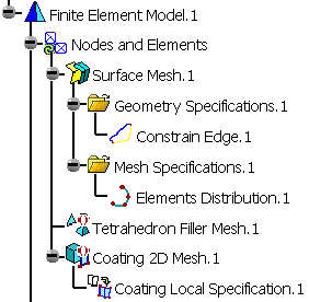
Mesh parts are stored under the Nodes and Elements set of a .CATAnalysis specification tree.
Symbol |
Meaning |
|
|
The Advanced Surface Mesh.2 mesh part is activated and updated. |
|
|
The Advanced Surface Mesh.2 mesh part is hidden (using the Hide/Show command). |
|
|
The mesh of the Advanced Surface Mesh.2 mesh part is
hidden (using the Hide/Show Mesh command). |
|
|
The Advanced Surface Mesh.2 mesh part is
deactivated. |
|
|
The Advanced Surface Mesh.2 mesh part is
non up-to-date. |
To know more about the specification tree elements, refer to Nodes and Elements.
Colors Meaning
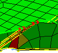
Colors Used for Element Quality
Color |
Meaning |
|
Green |
Used when the element are solved by the solver without any problem. |
|
Yellow |
Used when the element are solved by the solver with very few possible problems. |
|
Red |
Used when the element are hardly properly solved. |
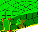
1D elements are also colored as described in the table.
In the case of null size connection bars, the quality colors are also applied and a symbol is displayed:
-
good quality: a point highlighted in green (
 )
) -
poor quality: a circle highlighted in yellow
-
bad quality: two circles highlighted in red (
 ).
).
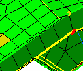
Colors Used for Edges and Vertices
Color |
Meaning |
|
Green |
Used for free edges and vertices, as well as holes. |
|
Yellow |
Used for edges/vertices that are shared between two constrained faces. |
|
Blue |
Used for edges/vertices that are shared between two non-constrained faces. |
|
Red |
Used for edges/vertices that are shared between more than two constrained faces. |
In the case of null size connection bars, the
representation is the following: ![]() .
.
Associativity
When you create a mesh part, you need to select a support, that can be either a geometry or an other mesh part.
If you modify the support of a mesh part (a geometry or a mesh part), the mesh part is also modified and the mesh part becomes non up-to-date. You will then need to update it.
Knowledgeware Capabilities
Any time you need to enter values in dialog boxes, you have access to knowledge capabilities. You can also modify local specifications using the Formula command.
To know more, refer to Accessing Knowledge Formulas and Parameters and Modifying Local Specifications with Knowledgeware.
Preprocessing Specifications and ELFINI Solver Compatibility
When a geometry is meshed, it is possible to apply to this geometry (and then to this mesh part) preprocessing specifications of the Generative Structural Analysis workbench (such as loads, restraints, properties, masses, ...) and to launch an ELFINI computation.
To know more about preprocessing specifications and ELFINI Solver, refer to the Generative Structural Analysis User's Guide.
Toolbars and Workshops
The Advanced Meshing Tools workbench contains toolbars dedicated to:
- Mesh creation (based on geometry or mesh part)
- Mesh quality
- Mesh visualization.
The Advanced Meshing Tools workbench also contains two workshops dedicated to surface mesh (Surface Mesher and Advanced Surface Mesher).
To know more about toolbars, refer to Workbench Description.


