|
|
-
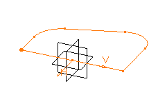
Select the profile if not already selected and click Pad
 .
.
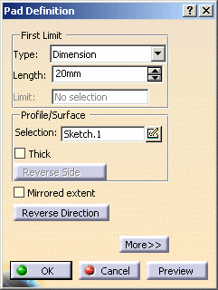
The Pad Definition dialog box appears. Default options allow you to create a basic pad.
-
As you prefer to create a larger pad, enter 60 mm in the Length field.
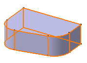
The application previews the pad to be created. -
Click OK.
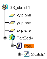
The pad is created. The extrusion is performed in a direction which is normal to the sketch plane. The application displays this creation in the specification tree:

The application lets you control the display of some of the part components. To know more about the components you can display or hide, refer to the General section that describes how to customize the Tree and Geometry Views.
For more about pads, refer to Creating Pads, Creating 'Up to Next' Pads, Creating 'Up to Last' Pads, Creating 'Up to Plane' Pads, Creating 'Up to Surface' Pads, and Creating Pads not Normal to Sketch Planes.
