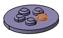
- Circular patterns
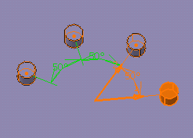
- Rectangular patterns
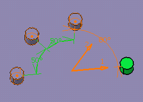
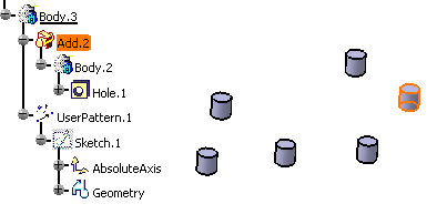
- User patterns
This task shows you how to duplicate geometry of one or more features right away at the location of your choice using a circular pattern.
This document also deals with:
You can also find information about patterns and updates by reading Optimizing Part Design Application, Patterns.
Open the CircularPattern.CATPart document.
-
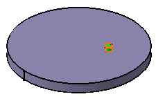
Select the pad whose geometry you wish to copy.
-
Click Circular Pattern
 .
.
The Circular Pattern Definition dialog box is displayed and the feature's name appears in the Object field.
If you change your mind and decide to pattern the current solid, click the Object field and use the Get current solid contextual menu item. For more information, refer to Patterning Current Solids.
Keeping Specifications
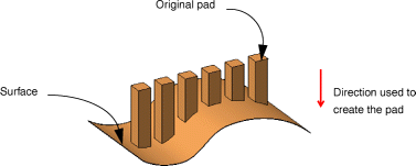
Checking the Keep specifications option creates instances with the limit Up to Next (Up to Last, Up to Plane or Up to Surface) defined for the original feature. The example below shows you that the limit defined for the pad, that is the Up to surface limit, applies to all instances. As the limiting surface is not planar, the instances have different lengths.
Parameters
The Parameters field lets you choose the type of parameters you wish to specify so that the application will be able to compute the location of the items copied.
These parameters are:
- Instances & total angle: the application computes the angular spacing after you specified the number of instances you wish to obtain and a total angle value.
- Instances & angular spacing: the application computes the total angle after you specified the number of instances you wish to obtain and an angular spacing.
- Angular spacing & total angle: the application computes the instances you can obtain by specifying an angular spacing and a total angle.
- Complete crown: the application computes the angular spacing between the instances you decide to obtain.
- Instances & unequal angular spacing: distinct angle values can be assigned between each instance.
- If you set Instances & total angle or Angular spacing & total angle parameters, note that you cannot define the total angle when using formulas.
-
The Keep specifications option is not available if you are patterning a pattern.
-
Set the Instances & Angular spacing options to define the parameters you wish to specify.
-
Enter 7 as the number of pads you wish to obtain.
-
Enter 50 degrees as the angular spacing.
Reference Direction
-
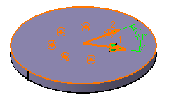
Click the Reference element field and select the upper face to determine the rotation axis. This axis will be normal to the face.
To define a direction, you can select an edge, a line, a planar face or a plane. After selecting an edge, a line or a planar face, if necessary, you can also select a point to define the rotation center. If you select a plane, selecting a point is mandatory.
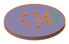
Two arrows are then displayed on the pad.
![]()
- Create Line: For more information, see Creating Lines.
- X Axis: the X axis of the current coordinate system origin (0,0,0) becomes the direction.
- Y Axis: the Y axis of the current coordinate system origin (0,0,0) becomes the direction.
- Z Axis: the Z axis of the current coordinate system origin (0,0,0) becomes the direction.
- Create Plane: see Creating Planes.
If you create any of these elements, the application then displays the corresponding icon next to the Reference element field. Clicking this icon enables you to edit the element.
-
Click Preview: the pad will be repeated six times. The instances are green, just like the original feature.
Crown Definition
-
Now, you are going to add a crown to your part. To do so, click the Crown Definition tab.
-
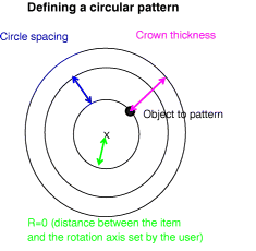
Set the Circle & Circle spacing options to define the parameters you wish to specify.
-
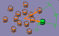
Enter 2 in the Circles field.
-
Enter -18 mm in the Circle spacing field.
This figure may help you to define your parameters:
-
Click OK.
These are your new instances: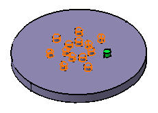
-
Now, you are going to modify the position of the initial pad. Such a modification will affect all instances too. Double-click the pattern.
-
Extend the dialog box by clicking More.
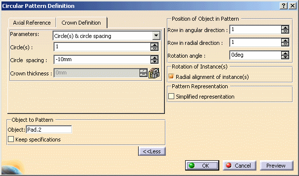
-
Enter 20 in the Rotation angle field.
The application previews the rotation.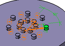
![]()
- Applying the Delete command on one instance deletes the whole pattern. However, deleting the instances of your choice is possible when creating or editing the pattern. To do so, just select the points materializing instances in the pattern preview. Selecting these points again will enable the application maintain the corresponding instances.
- The Simplified representation option lets you lighten the
pattern geometry. What you need to do is just check the option and
double-click the instances you do not want to see. The instances are then
represented in dashed lines during the pattern definition and then are no
longer visible after validating the pattern creation.
When the Simplified representation option is on, because the pattern's geometry representation is modified, the part mass is modified too.
This option is particularly used for patterns including a large number of instances. - Remember then that clicking once or double-clicking an instance does not lead to the same result.
-
Click OK.
All instances are moved accordingly.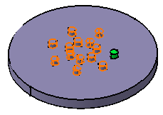


During your design, you may need to rework instances specifically. You will then have to use the Explode contextual menu item to delete your pattern while keeping geometry. For more information, refer to Exploding Patterns.

