|
How to Improve Update
Operations
-
Generally speaking, using the manual update
mode improves the application performance. To activate this option,
select Tools > Options, then in the Infrastructure >
Part Infrastructure category, check Manual from the
General tab.
- When working on large parts, you can improve the time necessary for
updating your geometry by customizing the Undo command
 .
What you need to do is restrict the number of commands that can be
undone for the current CATPart document. To do so, just select
Tools > Options, then in the General category, click
the Performance tab. In the Stack size field,
enter 0 to make sure that only local transactions of the current
command can be undone. This considerably reduces the time of update
operations. .
What you need to do is restrict the number of commands that can be
undone for the current CATPart document. To do so, just select
Tools > Options, then in the General category, click
the Performance tab. In the Stack size field,
enter 0 to make sure that only local transactions of the current
command can be undone. This considerably reduces the time of update
operations.
General Recommendations For Part Design Features
Pad, Pocket, Hole,
Shaft, Groove
To improve update performance, especially if you are working on
complex and large documents, we recommend you to:
- Set parameterized limits (Dimension option) for Pad,
Pocket and Hole features, as far as possible, instead of Up to
Next, Up to Last, Up to Plane, Up to
Surface options.
- Use closed profiles, as much as possible.
Holes
Editing center points may sometimes take a long
time. Whenever your design includes several holes which center points
need to be edited, we strongly recommend you define intermediate bodies
on which you create the holes. Using intermediate bodies is a way of
reducing the number of operations affected by
changes. Once intermediate bodies are created, just assemble them to the
part.
Patterns
Moreover, when working on patterns with a large number of instances,
to reduce update times :
- Remember that applying the
Keep Specifications Option is meaningless when you set the
Dimension option for the feature to be patterned.
- We recommend you to create the feature to be patterned as well as
the pattern feature into a new Body, then assemble the new Body with
the Part Body. Patterns created in that way are not affected by the
updates of previous operations.
The following scenarios illustrate the traditional method, then the
method we recommend.
Traditional Method
The user designed an up to surface pocket, then patterned it: updates
of the document take a long time.
Recommended Method
Using the recommended method, the user created a new body, set
a dimension for the pocket, patterned it, then assembled the body to the
Part Body: update times are greatly reduced because the update process
does not re-compute the new body (the application performs calculations
again if the geometry within the body is linked to the geometry outside
of the body, which is the case of constraints or use edges for example).
|
How to Improve Performance when Editing
You can improve performance when editing features by acting on the
application visualization settings:
- Activate the Only the current body option available via
Tools > Options, or just click Only Current Body
 in the Tools toolbar. For more information on the
capability, refer to the
Display
documentation of the Customizing section.
- Set values larger than the default ones to define 2D and 3D
accuracy for the geometry visualization. To do so, select Tools >
Options, then in the General > Display category, click
the Performance tab. Set the settings as explained in the
documentation of the Customizing Display section in the
Infrastructure User's Guide.
- When filleting, for example, it is often unnecessary to display
smooth edges. Therefore, hide them by clicking the Customize
View Parameters icon from the View
toolbar and checking the No smooth edges
option from the dialog box that appears. For more information, refer to
Customizing the View Mode in the Infrastructure User's Guide.
How to Improve Performance when Using the
Pre-selection Navigator
-
If you decide to use the Pre-selection
Navigator for selecting hidden elements, for example, you can improve
the application performance by checking the Display the
pre-selection Navigator after... seconds option and setting the
time delay to 2 or more seconds.
To access the option, select Tools > Options, then in the
General > Display category, click the Navigation
tab. For more information, refer to the documentation of the
Customizing Display section in the Infrastructure User's Guide.
How to Reduce Data Size
when Positioning Pasted Bodies
There are two ways of
positioning bodies you copied and then pasted using the As Result
With Link option.
-
By defining the position of the part within a product
(reference-instance link).
When the body is pasted, you cannot modify its position since it
inherits the position of the part. Consequently, to define a particular
location for the pasted body, you can apply transformation on it
afterwards.
-
By defining its location in relation to its reference
(reference-reference link).
At creation, not in a product context, it is possible to position the
pasted geometry in a non-associative way and this at a location different
from its reference. Using the compass does this.
In both ways, transformations are applied on the pasted bodies. The
problem is that each transformation duplicates the geometry data, which
may considerably increase the data size. To solve this problem, we
recommend the use of the Add Position...
contextual command.
Add Position
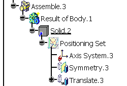
Add Position... creates a set called "Positioning Set"
associated with the pasted body, just below the Solid.x entity. In this
set, an axis system is added as a parameter. When you are applying
isometric transformations (such as Rotation,
Translation,
Symmetry etc.) onto the pasted geometry, apply in GSD workbench a
similar transformation onto this axis system. From a geometrical point of
view, the result is the same. This is just a way of reducing the data
size as well as maintaining the associativity of the pasted body's
position.
Note: the size of the CATPart document reduces only if the Solid is
complex enough.
In addition to performing these operations, the command also reroutes
existing transformations.
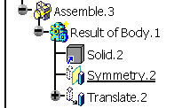
Before applying the Add Position... command
|
After applying the Add Position... command
|
 |
 |
|
|
Note: If a Positioning Set or any of its entities is defined as the
current object (defined in work object), the application visualizes only
these entities. All the other geometric elements are hidden in the
geometry area.
Deleting a Positioning Set
Deleting a positioning set as well as its content resets the import's
position. |
![]()