This task shows you how to create a rib, that is how to sweep a profile along a center curve to create material.
In this section, you will also find the following reference information:
Open the Rib.CATPart document.
-
Click Rib
 .
.
The Rib Definition dialog box is displayed.
-
Select the profile you wish to sweep, i.e. Sketch.2.
The profile has been designed in a plane normal to the plane used to define the center curve. It is a closed profile.
-
Select the center curve, i.e. Sketch.1.
The center curve is open. To create a rib you can use open profiles and closed center curves too. 3D Center curves must not be discontinuous in tangency.
You can also use planar wireframe geometry as your profile or center curve. -
To go on with our scenario, maintain Keep angle. This option keeps the angle value between the sketch plane used for the profile and the tangent of the center curve. Remember, the angle value is 90 degrees. When using Keep angle, it is recommended that the profile be on the center curve in a plane normal to the center curve. Otherwise, it may lead to an unpredictable shape. For more information, see Resulting Shapes.
The application now previews the rib to be created.
-
Click OK.
The rib is created. The specification tree mentions this creation.
-
Delete this rib to create another one by using Pulling direction. After setting this option, select plane xy to define z axis as the pulling direction. The plane used to define the profile will remain normal to plane xy.
The preview looks like this:
And the rib like this:
-
Delete this rib to create another rib by using Reference surface. First, display the multi-sections surface in the Show space, then set the Reference surface option and select the multi-sections as the reference surface. The angle value between the h axis of the profile and the surface equals 0. It remains constant.
The preview looks like this:
And the rib like this:
Thin Solids
-
Check the Thick Profile option to add thickness to both sides of Sketch.2. New options are then available:

-
Enter 2mm as Thickness1's value, and 5mm as Thickness2's value, then preview the result.
Material is added to each side of the profile.
-
To add material equally to both sides of the profile, check Neutral fiber and preview the result.
The thickness you defined for Thickness1 (2mm) is now evenly distributed: a thickness of 1mm has been added to each side of the profile.
-
Click OK to create the rib.
The rib looks like this:
How to Define a Rib
To define a rib, you need a center curve, a planar profile and possibly a reference element or a pulling direction. You can combine the different elements as follows:
| Closed Profile | Open Profile | ||
| Open Center Curve |
|
(Existing material) |
 (Thick Profile option, no existing material) |
|---|---|---|---|
|
(Thick Profile option, existing material) |
|||
| Closed Planar Center Curve |
 |
 (Thick Profile option, no existing material) |
|
| Closed 3D Center Curve |
 |
 (Thick Profile option) |
|

About Profiles
- In some cases, you can define whether you need the whole sketch, or sub-elements only. For more information, refer to Using the Sub-elements of a Sketch.
- Clicking the icon
 opens the Sketcher . You can then edit the profile. Once you have done
your modifications, you just need to quit the Sketcher. The Rib
Definition dialog box then reappears to let you finish your
design.
opens the Sketcher . You can then edit the profile. Once you have done
your modifications, you just need to quit the Sketcher. The Rib
Definition dialog box then reappears to let you finish your
design. - If you launch the Rib command with no profile previously
defined, just click the icon
to access the Sketcher and then sketch the profile you need.
-
You can also create your profile by using any of these creation contextual commands available from the Profile field:
-
Create Sketch: launches the Sketcher after selecting any plane, and lets you sketch the profile you need as explained in the Sketcher User's Guide.
-
Create Join: joins surfaces or curves. See Joining Surfaces or Curves.
-
Create Extract: generates separate elements from non-connex sub-elements. See Extracting Geometry.
If you create any of these elements, the application then displays the corresponding icon in front of the field. Clicking this icon enables you to edit the element.
-
If you have chosen to work in a hybrid design environment, the elements created on the fly via the contextual commands mentioned above are aggregated into sketch-based features.
- You can use an open profile provided existing material can trim the rib. For more information, refer to Trimming Ribs or Slots.
- Ribs can also be created from sketches including several profiles. These profiles must be closed and must not intersect. For example, you can easily obtain a pipe by using a sketch composed of two concentric circles:
|
|
|
| Profiles | Result |
Center Curves
Before using center curves, the following rules should be kept in mind:
- 3D center curves must be continuous in tangency
- If the center curve is planar, it can be discontinuous in tangency.
- center curves must not be composed of several geometric elements
Profile Control
You can control its position by choosing one of the following options:
- Keep angle: keeps the angle value between the sketch plane used for the profile and the tangent of the center curve.
- Pulling direction: sweeps the profile with respect to a specified direction. To define this direction, you can select a plane or an edge. For example, you need to use this option if your center curve is a helix. In this case, you will select the helix axis as the pulling direction.
- Reference surface: the angle value between axis h and the reference surface is constant.
- Contextual commands creating the directions
you need are available from the Selection field:
- Create Line: For more information, see Creating Lines.
- Create Plane: see Creating Planes.
- X Axis: the X axis of the current coordinate system origin (0,0,0) becomes the direction.
- Y Axis: the Y axis of the current coordinate system origin (0,0,0) becomes the direction.
- Z Axis: the Z axis of the current coordinate system origin (0,0,0) becomes the direction.
- Create Join: joins surfaces or curves. See Joining Surfaces or Curves.
- Create Extrapol: extrapolates surface boundaries or
curves. See
Extrapolating Surfaces and
Extrapolating Curves.
If you create any of these elements, the application then displays the corresponding icon in front of the Selection field. Clicking this icon enables you to edit the element.
If you have chosen to work in a hybrid design environment, the elements created on the fly via the contextual commands mentioned above are aggregated into sketch-based features.
-
Move
profile to path: easily associates profiles with center curves but
also allows a single sketch to be swept along multiple center curves.
This option can be accessed if Pulling direction of Reference surface is already on, and builds the profile with the following understanding:- The origin of the sketch plane (i.e. 0,0) will be swept along the path.
- The vertical axis of the sketch plane (i.e. 0,1) will be
kept parallel to either the pulling direction (if the profile control
is set to Pulling direction) or the normal to the
Reference surface (if profile control is set to Reference surface).
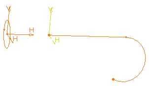
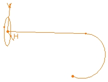
In this example, the profile to be swept is a square (shown by the arrow). The circles which belong to the same sketch are used as center curves and plane yz is set as the pulling direction. 
Once the geometry is selected and Move profile to path on: - the moved profile turns blue,
- a blue arrow is displayed at the origin of the transformed profile. Clicking on this arrow reverses the profile direction and rotates it 180 degrees about the pulling direction.
- an orange arrow is parallel to the pulling direction. Clicking on this arrow reverses the profile direction and rotates it 180 degrees about the blue arrow.
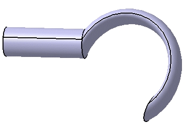
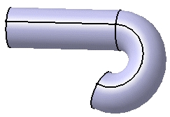
The resulting rib looks like this: 
Merge Rib's Ends
The Merge rib's ends option is to be used in specific cases. It trims each extremity of the rib to existing material, starting from the profile position until the first limit encountered on existing material in each direction. For more information, see Trimming Ribs or Slots.
Recommendation
It is recommended that the profile be on the center curve in a plane normal to the center curve. Otherwise, it very often leads to an unpredictable rib shape.
The position of the profile in relation to the center curve determines the shape of the resulting rib. When sweeping the profile, the application keeps the initial position of the profile in relation to the nearest point of the center curve. The application computes the rib from the position of the profile.
In both examples below, the application computes the intersection point between the plane of the profile and the center curve, then sweeps the profile from this position.
Keep in mind that when the profile is not on the center curve, even if you use any of the Profile control options (Keep angle, Pulling direction, Reference surface) , you cannot predict the final rib shape. The use of the Profile Control options never helps in anticipating the final rib shape. Consequently, it is preferable not to use such profile types.