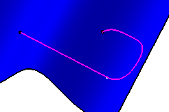
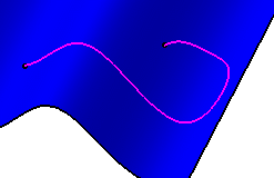
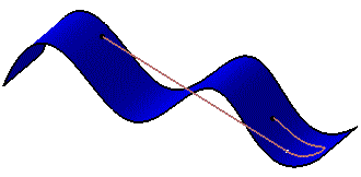
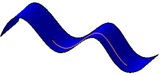
This task shows you how to extrapolate a curve.
Open the Extrapolate2.CATPart document.
-
Click Extrapolate
 .
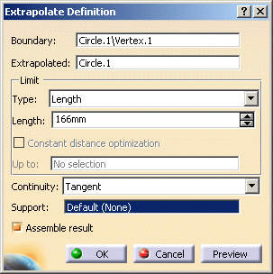
.The Extrapolate Definition dialog box appears. -
Select an endpoint on a curve.
-
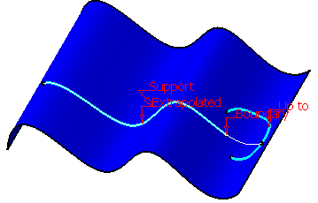
Select the curve to be Extrapolated (it can be a wire, an edge, a curve or a line).
-
Select the extrapolation type:
-
Length: enter the value in the Length field or use the manipulators in the 3D geometry.

It is not advised to enter a negative value in the Length field.

In Curvature mode, this length actually is the distance on the tangent extrapolation at which a plane normal to the curve is located. This plane is used to split the extrapolated curve. -
Up to: the Up to field is enabled. Select an element belonging to the same support as the curve to be extrapolated (curve, surface or plane).

The element must intersect the curve to be extrapolated.
-
-
Specify Continuity conditions:
-
Click OK to create the extrapolated curve.
The curve (identified as Extrapol.xxx) is added to the specification tree. 
Check Assemble result if you want the extrapolated curve to be assembled with the original curve.
![]()
