The dialog box and the operating mode are the same for all
components (whether in standard mode
or guided mode).
Components can be added to an
existing mold or
to an empty CATProduct.
Selective loading of plates is optimized.
![]()
Adding a component to an existing mold
- choose a first reference, (go directly to Positioning a component if a reference is already in use)
- position the component,
- drill holes,
- set the parameters values,
- define positioning constraints,
- activate a rule,
- Create a component in an empty CATProduct.
Choosing a first reference
-
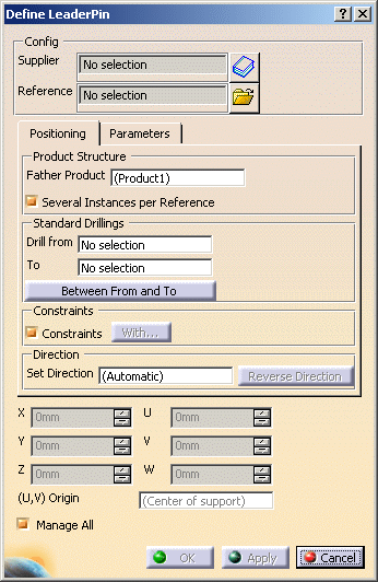
Click one of the component icons (here Add LeaderPin). The Define LeaderPin dialog box is displayed.
-
Click the catalog icon
 to access the catalog
browser.
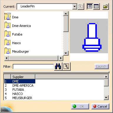
Select the catalog name, then the component type and the component reference:
double-click the required label to go to the next step, the last one reverting to the main dialog box,
with its Config fields updated with the Supplier name and the Reference of the component.
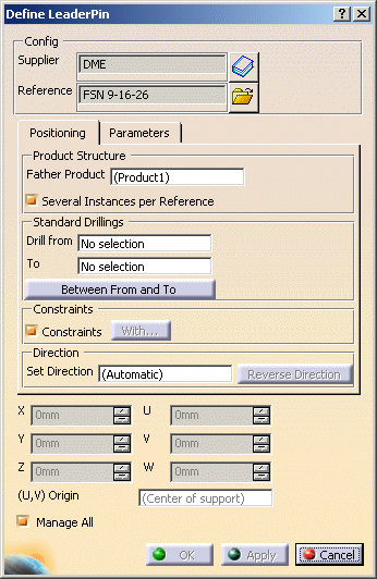
The Config area is a reminder of the reference of the component.
It can not be edited. You can only select another reference of a component of the same type, using the catalog icon ,
,
or select another reference from a file, using the File Open icon .
.
- Click the File Open icon
 in the dialog box and browse
your directories to that containing your component.
 - Select the component.
- You are then asked to position it, as in step 3 below.
- The Config fields are not updated.
Special case of the screws (CapScrew, CountersunkScrew, LockingScrew)
The operating mode is the same, but is enhanced by a smart filter in the
catalog.
If the To field is already defined, the distance between
the active preview location and the To plate is computed,
i.e. a
minimum and a maximum length are set for the screw.

The minimum and maximum lengths are set as filters for the Catalog
browser dialog box, applied to the L parameter of the screw,
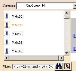
so that only references with appropriate lengths are proposed.
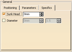
- The Sunk Head check box is selected by default and you can enter the value that you want the head to be sunk into the plate by (0 mm means that the head is flush with the plate surface),
- Select the Diameter check box to select a diameter
for the screw (to refine selection filtering):
- The first value is the diameter of the screw,
- The second value is the coefficient that defines the distance at which the tip of the screw will be sunk into the To plate (drilling destination plate).

but if we added that we wanted a screw with a diameter of 10mm, the selection to choose from would be much shorter:


you can then select any screw from the complete list.
Positioning the component
- Standard components are "smart" - they know where they should be in the specification tree when they are created. In some cases (e.g. angle pin, insert, fixing components, guiding components, locating components and spring), it is not automatic, the position of the components is determined by the information you give in the Drill from field. This allows the positioning constraint between the component and any plate.
- In the Tools, Options menu, then Mechanical Design, Mold Tooling Design customization dialog box, you can define a default plate positioning for the components. That way, when you create a new component of a customized type, it will be positioned automatically on the correct face of the correct plate, without previous picking.
- In the Tools/Options/Mechanical Design/Sketcher, activate the Position sketch plane parallel to screen option, or the Grid Snap to Point option if needed.
-
Select a face of a plate. The sketcher is displayed, with a manipulator to position the component.
The Drill from field is updated automatically with the name of the plate you have selected.
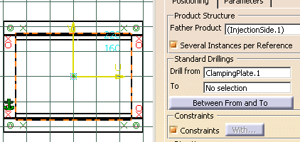
-
The grid is displayed. Pick where you want to position the component. The anchor point position is updated.
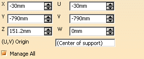
-
You can now define the coordinates of the new components by picking either:
- a 2D point on the face,
- a 2D point outside the face that will automatically be projected onto the face,
- a 2D point sketch on the face,
- a 2D point sketch outside the face that will automatically be projected onto the face,
- a 3D point on the face,
- a 3D point outside the face that will automatically be projected onto the face, or
- an axis, an edge, or a line that will automatically intersect with the selected face.
-
You can easily line up a new component with an existing one by picking the axis of the existing component when creating the new one.
-
You may then modify the coordinates values:
- by hand, if desired, using either the X, Y, Z coordinates or the U, V, W local coordinates.
- by using the arrows to move the component on the plane.
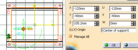
-
You may use the green arc to rotate the component around Z axis. It turns orange when active.
-
With the contextual menu Edit Angle, change the step and angle values of the rotation in the dialog box that is displayed:

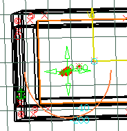
- The coordinates are displayed in the viewer and updated as you move the cursor.
- By default the axis of the component is perpendicular to the selected face. You can choose its orientation by picking a 3D line, an edge or the axis of another component before selecting the face, or use the Set Direction field at any time.
- When you select a plate to position a component, the Z+ axis of the component to create is always oriented inwards the material. This may not be true if you select a 3D pre-defined point.
- Defining the Drill from field and the To field in the dialog box before positioning the component will define the direction that is applied to the component axis.
- If the orientation of the component must be changed, the Drill From and To orientation is taken into account.
- If you select another reference, the pre-visualization is updated accordingly.
- When you insert a StopPin, the distance between the setting plate and the ejector plate is the same as the height of the StopPin. If you change the height of the StopPin, the distance between the two plates changes automatically. You can change the distance manually in the SPShH parameter in the specification tree.
Standard mold bases include 3D points that are identified as being for the location of components.
When the component is created on a 3D point you can change its orientation by picking a 3D line, an edge or the axis of another component, or use the Set Direction field at any time. If the selected axis is parallel, the position of the component is projected onto the intersection between the selected axis and the component reference plane; if not, the orientation of the component is modified according to the selected axis.
Positioning the component in guided axis mode
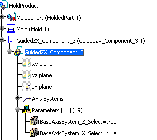
- BaseAxisSystem_X_Select
- BaseAxisSystem_Y_Select
- BaseAxisSystem_Z_Select
Then save the component.
-
Open file MoldProduct.CATProduct in the samples/PositionSlider directory.
-
Click Add User Component
 .
. -
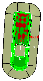
In the same directory, choose GuidedZX_Component.CATPart. A small x is displayed beside the cursor
indicating the position where the component is to be located. Click a point or an edge vertex.
-
A Z is displayed beside the cursor.
Choose an axis, edge or line to indicate the component's Z axis.

-
An X is displayed beside the cursor.
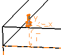
Choose an axis, edge or line to indicate the component's X axis.

-
Positioning is now complete. Click OK to create the component.
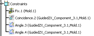 |
Drilling holes and positioning
- For all components but screws, open holes are drilled.
When dealing with screws, the type of hole depends on your selection for the Drill from and To locations:
- if only the Drill from location is defined, either as a plate or a component, a standard hole is drilled,
- if only the To location is defined, either as a plate or a component, a tapped blind hole is drilled,
- if both areas are defined, either as a plate or a component for each one, the hole is standard in the element set as the Drill from location and a tapped blind hole in the element set as the To location.
Except when you are working on a support, by default, the Drill from and To area are set to No selection (no hole drilled). If you wish to define the holes associated to the component, first select the fields Drill from or To in the dialog box, then pick a plate or a component in the graphic area to define the other reference plate.
- If you wish you can select the plate or component in the specification tree (expand the tree first and select the reference).
- When working with a support, selecting the plate updates automatically the Drill from field with the name of that plate.
- All plates located between the two reference plates are drilled as well.
- For all pads and pockets created by Adding or Removing Material: pockets are removed whereas pads are added in the Drill from (plate or component) area.
The Between From and To button has become
available.

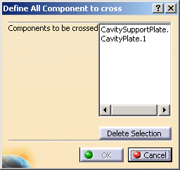
You can now select plates or other components found between the Drill from element and the To element:
-
select an element in the viewer to add it to the list of elements to be drilled,
-
select an element in the dialog box list and push the Delete Selection button to remove it from the list of elements to be drilled.
- If the From and To are Mold specific plates, the list between From and To contains the list of the plate between the From plate and the To plate excepted the From and To plate.
- If the From and To are not Mold specific plates, it is not possible for the application to list the plates between. The list is empty and you can add anything
- If the From and the To plate are not defined, the button named Between From To is not activated.
In the case of an offset, it is measured between the point/plane and the component's base point. The purpose of these constraints is to ensure that, if the positioning point is moved, the component will follow.
Depending on what you choose as positioning element(s) (point and/or plane), one or two constraints will be created.
- Only one constraint is created if you choose any type of point other than a point on plane. Only the offset between the component base point position and the positioning element will be ensured if the positioning element is moved.
- Two constraints will be created if you choose a plane and any point on it, or a point on plane. The offset between the component and the positioning element will be respected as will the component's axis.
For example, you have created a screw and you want its head to remain flush with the surface of a plate no matter what change you apply to the plate. If you set a constraint of 0mm with the top plane of the plate, you will be able to change the thickness of the plate and the screw head will remain flush with the surface.
- If you use both a point and a plane, we suggest that you select the plane first and then the point.
- If you do not wish to drill the plate being used to define the constraint immediately, click the Drill from field to replace the plate name with No Selection.
- The constraint can only be created if the component and the point/plane are both in the same block (injection side, ejection side or ejector system). Double-click it to activate it before creating the component. See the Assembly Design documentation for further information on constraint creation.
- Constraints that depend upon a component will be deleted if you edit that component.
- After moving a positioning point, you must update the viewer.
- You can define other constraints in the Assembly Design workbench.
To change the orientation of only one component, edit the component after having created it.
- The color of an associated hole is that of the element in which it is created. If you want to assign a specific color to some of the faces in an associated hole, you must modify the color of the features included in the bodies named DrillHole/TapHole. For example, if the DrillHole body of a component is composed of a blue feature hole and a red feature hole, the associated hole will have blue and red faces.
- If specific colors have been defined for associated holes of the component, these colors are applied to the resulting hole of the drilled element and are managed only through Mold Tooling commands. If you modify the position of the component by a command other than the Edit Component command, the colors are lost.
- When inserting a
component into a mold, you can reduce the time required to update your
mold by adapting your session settings. Go to
Tools>Options>Assembly Design>General. Choose to have an
Automatic Update
on the Active level (as shown below).
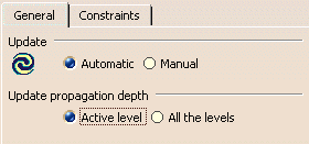
This automatically updates all of the parts of the model that are on the same level as the one currently active and not the entire mold (i.e. it updates the relevant part of the mold only and thus saves time). For further information see the General chapter on Customizing in the Assembly Design User's Guide.
Parameters
The Parameters tab is used to display the functional parameters of the components. They can be edited.
Example - Editing the Parameters for Fixing components
Those are the CapScrew, CountersunkScrew, LockingScrew.
You may need to edit their DrillHoleLength parameter. This parameter
manages the height of the hole from the head of the screw. You may need to
edit it because too long a hole has been created:

First, make sure the following options are checked:
Parameters in Part Infrastructure/Display tab
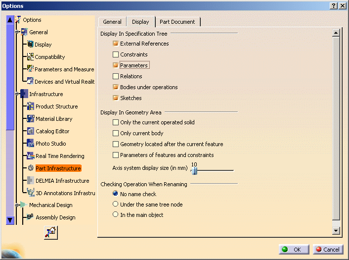
With value and With formula in the Parameters
and Measure/Knowledge tab
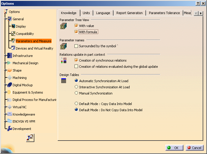
so that the Parameters section of the CapScrew is displayed in
the specification tree
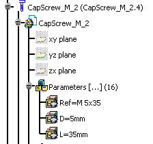
You will note that only three parameters are available in this section,
as in the CapScrew edition dialog box.
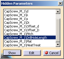
Now, right-click Parameters to launch its contextual menu and
select Hidden Parameters...

In the list that is displayed, select DrillHoleLength and click Show.
It is now displayed in the specification tree and in the dialog box.
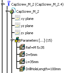
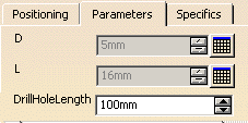
Now change the DrillHoleLength value to 16. The size of the hole is
modified.
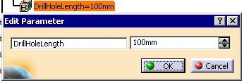
You could also double-click DrillHoleLength in the specification tree to
edit it directly.
Activate Rule
You can use an knowledgeware rule. This rule is stored in the rules catalog. It can be used to modify the geometry of a component, or to check its validity, ...
-
Click the catalog icon
 and select a rule.
 -
The name of the rule is displayed in the field to the left of the icon.
-
According to your needs, check the Activate Rule option to activate it as it is imported in the component.
Creating a Component in an Empty CATProduct
-
Select File/New and choose Product in the New dialog box.
-
Click Add Insert
 . The Insert dialog box is
displayed.
 -
Select the required Insert from the catalog As shown above.
-
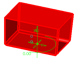
Click in the viewer where you want to place the origin of the instance.
The origin will be located on the view plane on the mouse pick, with an axis corresponding to the main OZ axis.
The spinners are updated with the coordinates values while you move the component with manipulators so that you can position it precisely.
-
Click OK to create the insert.
![]()