![]()
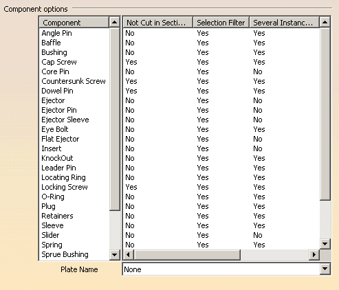
This tab deals with options concerning components, giving the components on the left and the customizing options on the right:

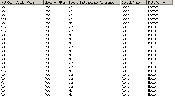
The full table of options looks like this:

-
The column 'Not cut in section views' is used to determine whether the component will be visualized in crosshatch display when a cut is being performed in its drafting.
By default, all types of screws (cap screws, countersunk screws, locking screws,...) and dowel pins are not cut; therefore the option is selected by default for these components
-
The column Selection filter allows the user to activate or not know-how rules when creating components. When activated, associated filters are applied in the Catalog Browser during component creation.
By default, the rules are automatically applied to all components:
- bushing: the value of the inner diameter of the bushing (InD) must correspond to the value of the leader pin 's tip diameter (D) if there is one.
The following filter is therefore activated: InD=D
- core pin: the overall length of the core pin (L) must be greater than or equal to H, the height between the bottom of EjectorPlateA and the top of the uncut CorePlate.
The following filter is therefore activated: L>=H
Also, the height of the core pin's guide hole is set by the Offset_Parting parameter.
- ejector: the overall length of the ejector (L) must be greater than or equal to H, the height between the bottom of EjectorPlateA and the top of the uncut CorePlate
The following filter is therefore activated: L>=H
Also, the height of the ejector's guide hole is set by the Offset_Parting parameter.
- ejector pin: the overall length of the ejector pin (L) must be greater than or equal to H, the height from the bottom of EjectorPlateA to the top of the uncut CorePlate.
The following filter is therefore activated: L>=H
Also, the height of the ejector pin's guide hole is set by the Offset_Parting parameter.
There is a check on the height value of the hole containing the ejector pin's shouldered part to determine whether it is consistent with the course of the ejection plates; an error message is displayed when there is a risk of collision.
- ejector sleeve: the overall length of the ejector sleeve (L) must be greater than or equal to H, the height from the bottom of EjectorPlateA to the top of the uncut CorePlate
The following filter is therefore activated: L>=H
Also, the height of the ejector sleeve's guide hole is set by the Offset_Parting parameter.
- flat ejector: the overall length of the flat ejector (L) must be greater than or equal toH, the height between the bottom of EjectorPlateA and the top of the uncut CorePlate.
The following filter is therefore activated: L>=H
Also, the height of the flat ejector's guide hole is set by the Offset_Parting parameter.
There is a check on the height value of the hole containing the flat ejector's shouldered part to determine whether it is consistent with the course of the ejection plates; an error message is displayed when there is a risk of collision
- leader pin: in the case of a standard mold base, use of the DLP diameter parameter (a mold base parameter which is displayed in the specification tree) is recommended by the supplier.
The following filter is therefore activated: D=DLP;
- locating ring: in the case of a standard mold base, use of the DLR diameter (a mold base parameter which is displayed in the specification tree) is recommended by the supplier.
The following filter is therefore activated: ShD=DLR
- sleeve: the inner diameter of the sleeve (InD) must correspond to the diameter of the leader pin (D) if there is one. The following filter is therefore activated: InD>=D
The length of the sleeve (L) must be greater than the height of the riser bars (H). The following filter is therefore activated: L>H.
One or two filters can be activated, depending on the current situation.
- stop pin: in the case of a standard mold base, use of the DSP diameter (a mold base parameter which is displayed in the specification tree) is recommended by the supplier.
The following filter is therefore activated: ShD=DSP
- support pillar: the length of a support pillar (L) must equal the height of the riser bars, i.e. the distance between SettingPlate and CoreSupportPlate or CorePlate.
The following filter is therefore activated: L=H
-
The column Several Instances per Reference is set to yes by default for all components (except for core pins, ejectors, ejector pins, flat ejectors, ejector sleeves , spring, sliders, and inserts). This is an option that allows you to create several instances of one reference component. If you deactivate this option, only one instance will be created per reference component.
-
The column Default plate defines a default plate for a given component. By default it is set to None. Select the component, then select a plate from the Plate name list at the bottom.
-
The column Plate Position defines a default positioning on a plate for a given component. By default, this option is set to Bottom. Click the label to change it to Top. First select the plate on which the component is to be positioned. The Top and Bottom option becomes available. Check the proper one. The next time you will create a component of this type, it will be positioned on the chosen plate, on the selected face, without selecting it.