- For CATProducts (Mold, InjectionSide, EjectionSide, EjectorSystem): Tools>Options>Infrastructure>Product Structure:
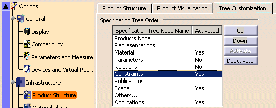
- For CATParts: Tools>Options>Infrastructure>Part Infrastructure:

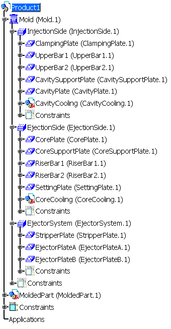
The compulsory names for plates are:
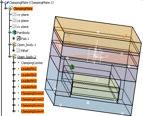
- ClampingPlate,
- UpperBar1, UpperBar2,
- CavitySupportPlate,
- CavityPlate,
- StripperPlate,
- CorePlate ,
- CoreSupportPlate,
- RiserBar1, RiserBar2,
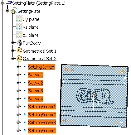
- SettingPlate,
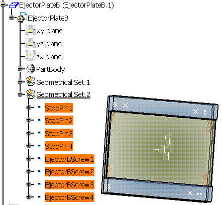
- EjectorPlateA, EjectorPlateB
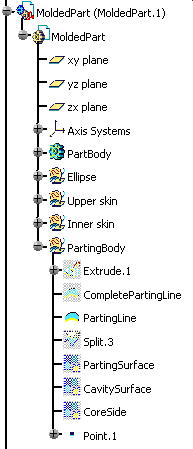

MoldedPart must contain the part to mold and all surfaces required for the core plate and cavity plate split. The Geometrical set containing the parting surface must be called PartingBody.
When splitting a component, all bodies included in the component will be split. If there is a body that you do not want to split, rename it with two underscores as a prefix (i.e. body1 becomes __body1).
If a surface named CavitySurface is found in the specification tree, it will be automatically proposed as the splitting element for the cavity plate.
If a surface named CoreSurface is found in the specification tree, it will be automatically proposed as the splitting element for the core plate.
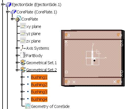
- bushings are called Bushingi (where i is a number from 1 to 4),
- cap or countersunk screws are called ClampingScrewi, SettingScrewi and EjectorBScrewi (where i is a number from 1 to 4),
- leader pins are called LeaderPini (where i is a number from 1 to 4),
- sleeves are called Sleevei (where i is a number from 1 to 4),
- stop pins are called StopPini (where i is a number from 1 to 4).

This is a CATPart with a special structure
Its name must be that used in the catalog (here SLIDER)
There must be an Geometrical set named PartBody containing the object itself.
There must be an Geometrical set named DrillHoll containing the negative shapes subtracted from the mold.
There must be an Geometrical set BaseBody containing a point named Base, with its coordinates being 0,0,0 to define the reference point of the component.
To add material around a component, you must create an Geometrical set named Pad.
To remove material around a component, you must create an Geometrical set named Pocket.

Sleeve_Z022_2 is inserted between the ClampingPlate in the InjectionSide and the SettingPlate in the EjectionSide. TlgItf_EjectionSide conveys the impact information from the InjectionSide to the EjectionSide.