| |
-
From the Simulation Analysis toolbar, click
Clash
 . .
-
In the Type lists, select Contact +
Clash from the top list and Between two selections in
the bottom list.
-
Click in the Selection 1 box.
-
In the PPR tree, select the T2 Face Mill D 50.
 |
| The Selection 1 box is updated. |
 |
-
Click in the Selection 2 box.
-
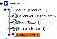
In the PPR tree, select Part4.
 |
| The Selection 2 box is updated. |
 |
-
In the Check Clash dialog box, click OK.
-
In the Simulation Analysis Tools toolbar,
click Analysis Configuration
 . .
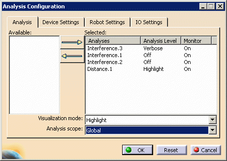
| The Analysis Configuration dialog box
appears. |
 |
 |
When you are executing the scenario described in this
procedure, the MeasureBetween.1 and MeasureEdge.1
analysis objects do not appear in the Available list. |
-
In the Available list, select
Interference.1, and press on the arrow button pointing to the
Selected box.
| Interference.1 appears in the Selected box. |
 |
-
Select Interference.1 and keep
selecting the value underneath
Analysis
Level until you find Highlight.
 |
With each click, the value toggles among the four
possible levels. |
 |
For information on the four possible levels, see
Configuring Analysis Objects. |
-
Click OK.
-
Click Analysis Mode
 . .
| When the command is highlighted, the Analysis Mode
is set to ON. |
-
In the PPR tree, select the Manufacturing Program.
-
To run the simulation again, click Machine
Simulation
 . .
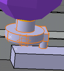
| If there is a collision, it is highlighted because you chose
this analysis mode above. |
 |
|


