DXF/DWG: Export

This task quickly shows you how to export the data contained in a CATDrawing document into a DXF file.
  • Drawing Interchange Format (DXF) files enable the interchange of drawings between
    Generative Drafting Version 5 and Version 4 or with other programs.
  • DXF files correspond to ASCII format and DWG to binary format.
  • V5 provides a simple method to export the data contained in a CATDrawing document
    either in a DXF file or in a DWG file.V5 supports DXF/DWG formats version 12, 13, 14 and AutoCAD2000.
You can find further information in the Advanced Tasks:
Open a CATDrawing document.
  1. Select the File, Save As item.

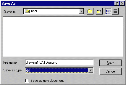
    The Save As dialog box is displayed:
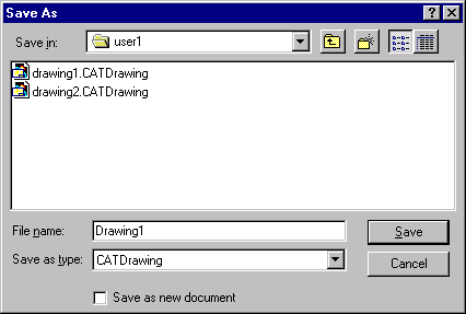
  2. Change the Format type into DXF type.

  3. Enter the file name.

  4. Click Save.

The export unit depends on the current unit of your session
(see the Tools > Options > Parameters and Measures/Units panel). 
  • If the current unit belongs to the metric system (millimeter, centimeter, meter, ...)
    the export unit is the millimeter.
  • If the current unit belongs to the Anglo-Saxon system (inch, foot, ...) the export unit is the inch.

So select the required type of session unit to export your data in one system or the other.

Limitations in the case of a multi-sheet drawing:

  • When there are several sheets, the name of the file really created is not that entered by the user in the
    Save as dialog box, since it is concatenated with that of the sheet. Therefore,  it is not possible to check
    if a file with the same name already exists and any existing file will be overwritten without warning.
  • If one of the sheets contains no geometry, no DXF file is created.
  • The number of characters of the name of the result file is limited to 150.
  • If the name of a sheet contains one of the following characters or a
    blank space, the character will be replaced with _ (underscore).
You can customize the DXF specific export options:

Report file

After the exporting data to DXF/DWG files, the system generates:

  • a report file (name_of_file.rpt) where you can find references about the quality of the transfer 

This file is created in a location referenced by 

  • the USERPROFILE variable on NT.
    Its default value is Profiles\\user\\Local Settings\\Application \Data\\Dassault Systemes\\CATReport
    on NT (user being you logon id)
  • the HOME variable on UNIX. Its default value is $HOME/CATReport on UNIX.

What About the Elements You Export?


Both export options:

  • If the sheet to export contains no geometry, or only non supported entities, no DXF/DWG file is generated.
  • The visual clipping of views is not yet supported.
  • Show/No Show:
    The V5 elements placed in the No Show are not exported. The visible elements are exported.
  • Filters:
    To avoid missing geometries at export, we recommend that you activate either the filter All Visible or the filter None.
  • Generative raster views are never exported.
 

Semantic export option only:

  • If the check box Export dimensions as Dimensions is not selected, all dimensions are exported as graphic blocks and are editable as such.
  • If the check box Export dimensions as Dimensions is selected, dimensions are exported as follows:
    • Circular, linear and angular dimensions are exported as true dimensions and editable as such.
    • The texts of those dimensions are exported with the STANDARD style and the isocp.shx font.
    • The tolerances of dimensions are now exported.
    • The "upper" and "down" texts are not taken into account.
    • Dual values are not exported.
    • Circular extension lines are not exported.
    • Half-dimensions are exported as graphic blocks.
    • Chamfer dimensions are exported as graphic blocks.
    • Dimensions that cannot be exported semantically are exported as graphic blocks.
  • Layers are automatically exported.
    See Export layer name or Export layer number for more information.

  • Texts:
    • All texts are exported as texts (even dimension texts and annotations) with a fit justification,
    • All texts are exported with the STANDARD style and the isocp.shx font with the exception of geometric
      tolerance symbols that are exported with the GDT specific style and gdt.shx font, with the corresponding mapping.
    • The symbols diameter Ø, degree °, plus/minus ± are inserted with the standard tags. 
    • Unicode characters are exported with the \U+ tag.
      You have to redefine the STANDARD style in AutoCAD to reference an unicode font.

The table below sets the mapping between the CATDrawing file elements and the resulting DXF 2D elements.


V5 DXF/DWG
Element Sub-type Graphic export Semantic export
 

Structures

  Sheet One DXF file per sheet (see option)

The graphical representation of each file is transferred to the space of the AutoCAD model

  Views Interactive view

The structure is not exported. 


The structure is not exported.
Generative view The structure is not exported. All the geometric entities of the view are gathered into a single Insert/Block.

The above applies to CGR, approximate, exact views.

  Detail (2D Component) Details are retrieved through their Dittos. A Detail not referenced by a Ditto is thus lost, a Detail referenced by several Dittos is duplicated in BLOCKS. The entities included in a Detail are not structured into sub-blocks.
  Ditto (Instance of 2D component) The graphical representation of each Ditto is exported to an INSERT/BLOCK
 

Attributes

Unit The unit of the output file depends on the session current unit
Show/NoShow Only visible elements are exported
Pick/NoPick NoPick ignored
Line Type Automatic mapping
Line Thickness Automatic mapping
Marker type Ignored
Color Automatic color
  Text attributes Font

Exported implicitly through the graphic representation of text.

Default mapping with font isocp.shx (fixed)
For Kanji or unicode characters see Trouble Shooting
Bold, italic Not supported
Underlined Text + line
  Space (x-scale) Space
Height Height
Justification Justification
Flip Flip
Frame Text + geometry
Layer Not supported Layer
Semantic mode lets you decide to export V5 layer name as a number or a name
 

Annotations

  Dimension Linear

Circular

Angular


The geometrical basic elements of each representation are exported

Semantic mode:

Linear, angular and circular dimensions are exported as such.
On option, each graphical representation of the elements is exported to an INSERT/BLOCK

Curvilinear In both modes, each graphical representation of the elements is exported to an INSERT/BLOCK
Axis line Line with the suitable line type
Center Line

Each graphical representation of the elements is exported to an INSERT/BLOCK

Thread
Welding symbol
  Coordinate dimension
Balloon
Datum Target
Datum Feature
GDT
  Roughness symbol
Table
Leader
Arrow
Callout
Text   Only the contour of characters is exported as a 2D POLYLINE One TEXT (or several TEXTS in case of font or attribute changes) + geometry gathered into an INSERT/BLOCK (see text attributes)
  Area fill

Hatching pattern The geometrical basic elements of each representation are exported The geometrical elements making the hatches are gathered into an INSERT/BLOCK
Dotting pattern
  Image
pattern
Only the contour of the hatches is exported Only the contour of the hatches is exported into an INSERT/BLOCK
Coloring pattern The coloring pattern is exported as a set of SOLIDS The coloring pattern is exported as a set of SOLIDS gathered into one INSERT/BLOCK.
 

Geometry

Curve Point POINT
Line LINE
Polyline 2D POLYLINE
Circle CIRCLE
Arc ARC
  Spline

2D POLYLINE

If the Version is set to DXF/DWG R12 or R13, they are exported as 2D POLYLINE.

If the Version is set to DXF/DWG R14 or above:

  • Splines or NURBS originated from Interactive Drafting and Splines originated from exact views of Generative Drafting are exported into DXF Splines (with consistent graphical attribute such as color, line thickness and line type).

  • The Spline or NURBS inside a 2D Component are not managed (they are still exported as 2D POLYLINE).

Only the generative exact view can contain Spline or NURBS.

NURBS
Ellipse 2D POLYLINE or ELLIPSE
Hyperbola 2D POLYLINE
Parabola 2D POLYLINE
Constraints Not supported
 

Miscellaneous

OLE link Not supported
  Picture (bitmap...) Not supported