- Import DXF/DWG options:
- Export DXF/DWG options:
Import
Standards

Drafting:
The element you import will be placed in a Drawing, the root
document of Drafting.
This Drawing uses styles defined in a pre-defined or a customized
standard such as ISO, JIS, ANSI, ASME.
For more details about Drafting standards, please refer to
Administration Tasks in the Interactive
Drafting User's Guide.
Drafting Standards replace the process of the previous
releases where you had to open, (eventually modify)
and close a new Drawing to recover the standard you wanted to use for the
data you were going to import.
The standard selected in the settings is taken into account at once.
DXF:
DXF Standards replace the mapping options of the previous
releases.
Those options applied only to the current session whereas a given standard
applies to all the sessions
using that standard.
For more information, please refer to the Infrastructure User's Guide
Customizing Standards.
Some AutoCAD elements require a mapping:
- AutoCAD color is mapped to V5 line thickness,
- AutoCAD line type is mapped to V5 line type,
- AutoCAD text font is mapped to V5 text font.
These mappings are defined in a DXF standard file. For more details about
DXF standards,
please refer to DXF/DWG: Administration Tasks in this User's Guide.
Select the requested standards from the drop-down lists.
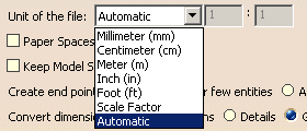
Unit of the File

(either millimeter or inch) for the best possible resulting drawing.
However, in some cases the resulting drawing is not satisfactory and requires another unit.
Select this unit in the list. Then restart the import.
If you have selected Scale Factor, enter the value of the scale factor between the imported
file and what you want to get from the original Drawing in the fields on the right.
Paper Spaces and Model Space
The Interactive Drafting workbench provides a simple method to manipulate a sheet. A sheet contains:
- a main view: a view which supports the geometry directly created in the sheet
- a background view: a view dedicated to frames and title blocks
- interactive or generated views.
An AutoCAD file is usually made of:
- a model space that contains the geometry,
- a paper space (or several in AutoCAD 2000 and above).
AutoCAD recommends that the paper space contains the title box and one or several viewports
(A viewport is a window to the model space). However other configurations are possible.
Select this option to put the Paper Spaces in the Background view.
The viewports will be created in the working view.
By default, this option is not selected.
Select this option to keep the entire Model Space in its own
sheet.
By default, this option is not selected.
If the option is not selected:
-
when the model space is referenced at least partially by one or several viewports, it will not be created in its own sheet,
-
when the model space is referenced by no viewport (or if there is no viewport in the DXF file), it will be created in its own sheet (unless it is empty).
If the option is selected:
-
the model space will be created in its own sheet (unless it is empty).
Create end points
![]()
It is not easy to modify and stretch geometry of imported elements the
way you can do it in a V5 native elements.
A solution is to create end points when needed, but to the detriment of
performances.
Create end points offers you three options to fit your needs:
- Never: it is the default option. It ensures the best performances.
- For few entities: creates end points only for hatch
boundaries and mixed polylines.
This is an intermediate choice between performances and edition capabilities. - Always: creates end points for arcs, ellipses, lines,
mlines, leaders and not standard polylines and splines.
Use this option only when edition capabilities are required.

Information on the option selected is given in the report file:

Convert dimensions as
Select the required option:
This option preserves the semantic of AutoCAD dimensions in V5 as best as possible.
- In most cases, the whole semantic of the dimension is kept.
This means the position, the layout and the text are preserved.
The position, color, thickness, text caption (symbol, value, tolerance, font, color) can be edited. - In some cases, text with redundant information
(e.g. tolerance present both in the dimension field and in the dimension text) or dual dimension,
or other unrecognized information will be dealt as a text with an associative link with the dimension.
This dimension has a "fake value" that is blanked.
To display the true dimension value, delete the associated text and enter the data in the properties
of the dimension.
- Angular dimensions, problems may occur while positioning texts,
- Following attributes are not yet supported :
- suppression of one of the dimension lines (for half dimensioning),
- offset extension or suppression of extension lines,
- arrowhead choice (the default arrowhead of the Drafting standard is used),
- automatic suppression of arrowheads if space is not sufficient.
Select this option to keep the graphical aspect. Geometry is exploded into multiple lines, arcs, texts.
(this mode increases performance when loading a model).
This is the option by default
This is an halfway notion between the previous two, in which the geometry is preserved and
the dimension is easy to handle (it can be all selected at once).
See also the FAQ
Export
Version

Select the required export file format from the combo box.
Autocad2000i and Autocad2002 formats are the same as Autocad 2000.
Exported Sheets
![]()
Select the required option to export either all sheets or only the current sheet of a multi-sheet drawing.
- The option Only current exports the data to a file with the name entered in the Save as dialog box.
- The option All exports the data to several files.
The name of each file is made of the name entered in the Save as dialog box and the name of the sheet
(Drawing1_sheet_1.DXF, Drawing_sheet_2.DXF, ...).
Export mode
![]()
This option offers the choice between two export modes:
-
Graphic:
This mode is quick and reliable. It is useful if you want to export a CATDrawing to AutoCAD and print it without modifying it. -
Semantic:
The exported file can be modified.
The Semantic mode offers the following
options:

-
Export dimensions as Dimensions:
If you select this check box, linear, angular and circular dimensions are exported as true dimensions (with a default dimension style).
Default dimension style entails that most graphic attributes
(such as color, display format of the dimension value, type of arrow, space...) of the dimensions are lost.
With the exception the None layer, each V5 layer is defined by three data:
-
Its number,
-
An optional name,
-
An optional comment.
In AutoCAD applications, layers are defined by:
-
a name,
-
a status,
-
some graphical attributes.
You can choose how you want to export layer number:
-
Export layer number:
Each V5 layer is exported with an AutoCad layer name that is the number of the V5 layer -
Export layer name:
-
If the V5 layer name is an empty string, the V5 number is exported (whenever the AutoCAD export version chosen).
-
If AutoCAD R12, R13 or R14 is selected as the export version, then only the first 26 characters are exported.
The only characters exported are:-
letters (from 'a' to 'b' and from 'A' to 'Z') all converted in upper case,
-
digits (from '0' to '9')
-
and the following special characters: the hyphen '-' and the underscore '_'.
-
All others characters are exported as underscore '_'.
-
-
If AutoCAD 2000 is selected as the export version, then only the first 255 characters are exported, with the same constraint about characters as above,
except that lower case letters are not changed to uppercase letters.
Some different layers could be translated into the same AutoCAD Layer. When this case happens a message is added inside the report file.
-