 |
This task lets you quickly see how to import or to insert
the 2D geometric data
contained in a DXF file into a CATDrawing document.
Once imported, the data can be handled and edited just as if they had been
created
in a Drafting session using 2D geometry creation commands.
The table entitled What about
the elements you import ? provides information on the entities you can
import.
You can find further information in the Advanced Tasks:
Statistics about each import operation can be found in the
report file created. |
 |
Open your session (Open your CATDrawing document if you want
to insert a DXF file.). |
 |
-
To import an existing DXF/DWG file, select the File >
Open items or
To insert a DXF/DWG file in an existing CATDrawing document, select the
Tools > Import From File.
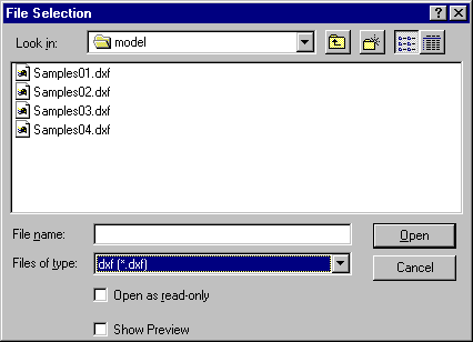
The File Selection dialog box is displayed:
-
Select the .DXF/.DWG
extension from the field called Files of type.
All .DXF/.DWG files contained in the selected directory are now displayed.
-
Click the .DXF/.DWG file of your choice.
-
Click Open.
- In import mode, a CATDrawing file is created which contains all
the geometry included in the DXF/DWG file. This CATDrawing file
becomes the current document.
- In insertion mode, the geometry of the DXF/DWG file is created
in the current drawing.
|
|
| |
The default behavior has been improved for better results.
If the model
is referenced, at least partially,
by one or several viewports, the model is not created in a sheet of its own.
Only layouts are created.
They will contain eventual viewports.
In this case, select the option
Keep model space to force the creation of the model space in its
own sheet.
CATIA does not create empty viewports or layouts. |
 |
Viewport with a not null twist angle (group code 51) are not correctly
handled during import. |
| |
V5 determines systematically and automatically the most suitable format
(A0 ISO, A1 ISO, etc.)
for each sheet (layout) i.e. V5 chooses the smallest format in which the
drawing can be totally included:
- If the standard is ISO, V5 chooses the format among A0, A1, A2, etc.
- If the standard is ANSI, V5 chooses the format among A, B, C, etc.
- If no standard format fits the sheet, the format is set to the largest
one i.e. A0 ISO and
made invisible with a message "No standard format can be applied to this
sheet" in the report file.
- If you are not satisfied with this automatic result, use the Page
Setup command to modify the format.
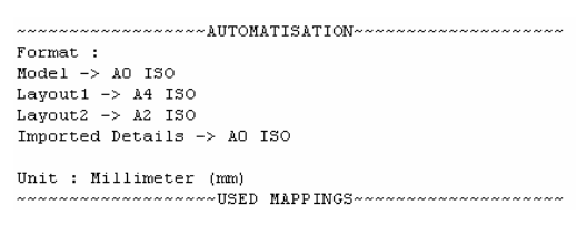
Information on what has been determined automatically is written in the
report file:

For more information on Formats,
see the Defining a Sheet chapter in the Generative Drafting User's Guide.
|
| |
Code pages
DBCS (Double Byte Character Set) Supported Code Pages are:
- 932 (Japanese)
- 936 (Simplified Chinese)
- 950 (Traditional Chinese)
|
 |
949 (Korean) is not supported. |
| |
Customization
Import of a DXF/DWG file can be improved by
customization:
DXF/DWG specific import settings are:
-
Standards. The lists of attributes are not the same in V5 and AutoCAD.
A DXF mapping standard file is used to come as close as possible to the
AutoCAD attributes,
or to switch them to V5 attributes.
-
Unit of the file
The definitions of dimensions are not the same in V5 and AutoCAD.
This option is used to give priority either to the graphic closeness or to
the re-usability in V5. |
|
 |
To make sure the elements you need to handle in your session are those you
expected,
here is a list presenting the DXF/DWG data supported when imported into a
CATDrawing file.
| |
DXF/DWG element |
DXF/DWG sub-type |
V5 element |
Notes |
| |
Geometry |
| |
point |
 |
Point |
 |
| |
line |
 |
Line |
 |
| |
ray |
 |
None |
 |
| |
xline |
 |
None |
 |
| |
circle |
 |
Circle |
 |
| |
arc |
 |
Arc |
 |
| |
ellipse |
 |
Ellipse |
 |
| |
polyline/2D polyline/
lightweight polyline |
non adjustable width,
made of line segments |
Polyline |
Not editable in V5 |
| |
 |
non adjustable width,
made of line and arc segments |
segments and arc
with no structure |
Structure is lost |
| |
 |
adjustable width |
Filled area (pattern) |
Structure is lost |
| |
 |
fit curve |
Polyline |
 |
| |
mline |
 |
Lines |
Structure and closing attributes are lost |
| |
spline |
 |
NURBS |
Not editable in V5 |
| |
3D face |
 |
none |
 |
| |
3D solid |
 |
none |
 |
| |
Annotations |
| |
text |
 |
Text |
 |
| |
mtext |
 |
Text |
Changing fonts, changing attributes and
line break are not taken into account |
| |
Arc aligned text |
 |
none |
 |
| |
rtext |
 |
none |
 |
| |
dimensions |
aligned,
linear and rotated,
radius and diameter,
angular, ordinate (x or y) |
According to option:
dimension or
details or
geometry+texts |
See
dimensions
In a few "dimensions" cases, the text of the
dimension can be a text with an associative link
In all "dimensions" cases, the geometry support is
in No Show |
| |
leader |
 |
Line + text |
DXF Leaders are imported as simple lines.
The arrow head and the line under the text are lost |
| |
tolerance |
 |
none |
 |
| |
hatch |
non-associative |
Filled area (pattern) |
|
| |
 |
associative |
Filled area (pattern) |
The contour of the hatch is created in the No Show
and the associativity is created with this hidden contour. |
| |
solid |
 |
Filled area (colored) |
 |
| |
block attribute |
 |
Text |
 |
| |
Structures |
| |
block |
 |
Detail
(2D component) |
The details are created in a new Detail Sheet
named "Imported Details". |
| |
insert (Block Reference) |
 |
Ditto
(instance of 2D component) |
If the insert is defined with different scales,
on x-axis and y-axis, no detail instance is created
but only the geometry is transferred. |
| |
external reference |
|
|
not supported |
| |
group |
 |
none |
The structure of the group
is lost whereas its contents
is transferred |
| |
viewport |
 |
View |
see
above |
| |
Layout (paper space) |
|
Sheet |
see
above |
| |
OLE frame |
 |
none |
 |
 |
|
|
|
|
| |
region |
 |
none |
 |
| |
Attributes |
| |
color |
 |
Color |
see
Standards |
| |
Line weight |
 |
Line thickness |
see
Standards |
| |
line type |
 |
Line type |
see
Standards |
| |
point markers |
 |
Point type |
Markers may be different since V5 and
AutoCAD do not have the same markers. |
| |
layer |
 |
Layer |
Invisible layers are gathered in a filter
named Invisible Imported Layers.
Visible layers are gathered in a filter
named Visible Imported Layers. |
|
|
layer name |
|
|
When an AutoCAD layer has a name that corresponds to
a number between 0 and 999, this layer will be imported as a V5 layer with
the number associated:
- if a V5 layer with the same number already exists, the AutoCAD
layer is imported in this V5 layer, without changing its name.
- if there is no V5 layer with the same number, the AutoCAD layer
is imported in a new V5 layer, with the same name as in AutoCAD.
If the AutoCAD layer has a name that does not match any number
in the available range, the layer is mapped on the first existing V5 layer
that has the same name, or a new one is created on the first available V5
layer number with the AutoCAD layer name.
|
| |
font |
 |
Font |
see
Standards |
| |
Pattern |
 |
Pattern |
Automatic mapping |
| |
BYBlock attribute |
 |
Attribute |
The value of the attribute of the block is
set to a default value |
| |
BYLAYER attribute |
 |
Attribute |
The value of the attribute of the layer is
applied to each element imported |


![]()