This is done using the FLEX algorithm. Based on bundle segment properties (length, diameter, etc.), CATIA computes the effective Young modulus and other input needed by the algorithm (cross section shape, flexibility). The algorithm takes into account protective coverings, internal splices as well as wires and wire groups:
- If no wires nor wire groups are routed, bundle segment stiffness is based on individual bundle segment flexibility
- If wires and wire groups are routed, bundle segment stiffness is based on the properties of the wires and wire groups. In this case, individual bundle segment flexibility is ignored.
If no FLEX solution can be found, a message informs the user and the standard algorithm is used.
The electrical designer can take advantage of all the benefits of the FLEX algorithm while working in exactly the same way as with the standard algorithm.
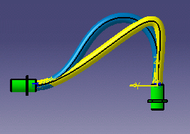 |
Legend:
|
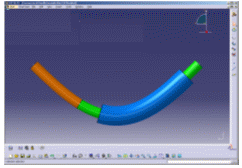
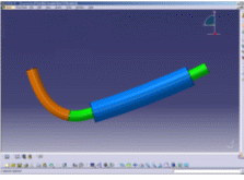
| Protective coverings add stiffness. This is taken into account by the FLEX algorithm. |
|
| Standard algorithm: | FLEX algorithm: |
 |
 |
| Internal splices add
stiffness. The FLEX algorithm takes into account the values for the
length and equivalent thickness attributes entered when defining
splices in Electrical Library. Notes:
|
|
For more information on this product, see Flex Physical Simulation Overview.
Designing from Scratch
-
Set the bundle segment computation mode to FLEX algorithm and adjust the balance slider.
-
Select the Work with one multi-branchable per geometrical bundle option under Tools > Options > Equipments & Systems > Electrical Harness Discipline > Electrical Harness Installation > Harness Management tab
-
Create a geometrical bundle.
-
Click Multi-Branchable Document
 and set branch parameters in the dialog box that opens.
The Electrical Harness Assembly workbench switches to the Electrical Harness Installation workbench. The Branch Definition dialog box opens. 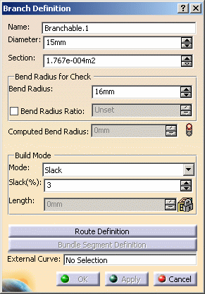
For information on standard options in the dialog box, see Creating a New Multi-Branchable Document and First Branch.

Note that the final slack, length and bend values may not exactly correspond to the user input due to the fact that the FLEX algorithm is a finite-element algorithm. If this is the case, it can be seen when you change the build mode. Computing the length of bundle segments in Bend or Slack modes:
- In order to obtain the closest possible correspondence in length when using either standard or FLEX algorithms, the computed length in Bend and Slack modes takes into consideration the bend radius in order to obtain an even more realistic bundle segment shape.
- Since the estimated shortest length (corresponding to a slack value of 0) is not directly computed using the FLEX algorithm, the user can enter a smaller input length when in Length mode. A negative slack value will be displayed in the Slack(%) box.
-
Click Route Definition and route a bundle segment.
-
Click Apply in the Branch Definition dialog box to compute the bend radius.
Computed Bend Radius
In FLEX mode, since the algorithm takes the physical properties of the bundle segment (such as diameter, etc.) as input, rather than purely mathematical parameters, CATIA computes the effective minimum bend radius. The bend radius, which is therefore no longer an input, is an attribute of the bundle segment used for checks and can be accessed in knowledge tools.
Status lights show whether or not the computed bend radius satisfies the minimum bend radius entered.
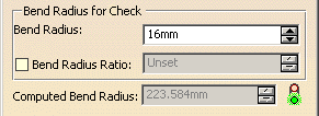

Another build mode becomes available after you have routed a bundle segment: Constrained length Build Mode - Constrained Length
The constrained length mode helps you minimize the impact on manufacturing. For example, in this mode, modifying the position of a support in the 3D view will not modify the flattened view or the harness drawing.
This mode lets you keep the same bundle segment length between points, branch points, supports and devices during harness design and modification, when moving, replacing or deleting a support, device or point.
For example, move this support... 
and the length of the bundle segment does not change:


In this mode, you can set the percent tolerance permitted between the initial and final bundle segment length. For example, if you set this value to 1 and the bundle segment is 100 mm long, then a final length of 101 mm will be tolerated. Note: In Constrained Length mode, the default accuracy is set to a very high value so that same bundle segment length can be maintained. The value set for the balance slider is not taken into account.
A message informs you if the modification in bundle segment length exceeds the tolerance and identifies for which branch this is the case. 
This build mode is recommended once you are well advanced in your design because, in this mode, you cannot: - add slack, supports, devices or branch points
- split bundle segments
- modify the length of a branch
- move a branch point
since these actions impact the length of the bundle segment and CATIA cannot figure out how the user intends to modify this length.
-
Click Bundle Segment Definition and set bundle segment parameters in the dialog box that opens.
Managing Slack Locally
You can add slack locally at
a specific location using the Local Slack command
![]() .
However, the Ignore Slack option is not supported by the
FLEX algorithm and is not available in the Local Slack Management
dialog box.
.
However, the Ignore Slack option is not supported by the
FLEX algorithm and is not available in the Local Slack Management
dialog box.
Updating an Existing Harness
-
Set the bundle segment computation mode to FLEX algorithm and adjust the balance slider.
-
Select Tools > Recompute All Bundle Segments.
All bundle segments are highlighted in red in the geometry area. They need to be updated. -
Select Update
 to rebuild bundle segments using the FLEX algorithm.
- If no FLEX solution can be found, a message informs the user and the standard algorithm is used.
- You can undo the recompute operation before or after the update.
- If you update branches with internal splices that were designed in earlier releases, the branch shape may be slightly different from that obtained previously because the FLEX algorithm takes internal splices into account.