 |
-
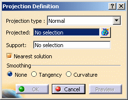
Click Projection
 . .
-
Select Normal as Projection type.
-
Select Translate.1 as first element to be
Projected.
 |
- If one element is selected
and you select another element, it automatically replaces the
element you selected previously, providing the multi-selection
panel is closed.
- If several elements are selected and you select
another element, it is appended to the elements list.
|
The selected
element (here Translate.1) is highlighted in the specification tree
and in the 3D geometry.
When you select or edit an element aggregated under the
multi-output node, either in the specification tree or in the 3D
geometry, its input is highlighted in the 3D geometry, in the
specification tree, and in the multi-selection panel.
In our example, Project.1 has Translate.1 as input, therefore when
you select Project.1 in the specification tree, Translate.1 is
highlighted in the 3D geometry, in the specification tree and in
the multi-selection panel. |
-
Click  to add elements.
| The multi-selection dialog box (here Projected)
opens. |
 |
Multi-selection is now active:
all selected elements are displayed in the dialog box. |
-
Select Translate.2.
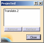 |
| Click Remove and Replace to
modify the elements list. |
 |
-
You can
select an element in the list: it is highlighted in the
specification tree and in the 3D geometry.
-
You can select one or more geometrical
sets and multi-outputs as inputs of the multi-selection.
In that case, all their direct children are selected.
|
 |
Clicking Remove deletes the
output feature. Therefore adding a new element in the list creates
a new output feature. Click Replace instead to replace
an input element by another without deleting the output feature.
|
-
Click Close to return to the Projection
Definition dialog box.
-
Select Extrude.1 as the Support element.
-
Click OK to create the projection elements.
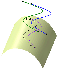 |
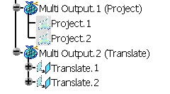
| The projection is identified as Multi Output.1
(Project) in the specification tree. |
| The created elements are aggregated under Multi
Output.1. |
 |
 |
You can create several multi-outputs in the
specification tree, each one grouping one type of elements. |
-
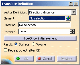
Click Translate
 . .
| The Translate Definition dialog box appears. |
 |
-
Select Translate.1 and Translate.2 as Element
to be translated.
-
Select Direction, distance as the Vector
Definition.
-
Select Extract.2 as the Direction.
-
Select -50mm as the Distance.
-
Click OK to create the translated element.
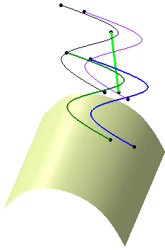 |
| The translation is identified as Multi Output.2 (Translate) in
the specification tree and appears below Multi Output.1. |
| The created elements are aggregated under Multi Output.2. |
 |
- When editing a multi-output, you can only select the elements
belonging to the multi-output in the specification tree (not in
the 3D geometry).
- When one or several elements are in
error under a multi-output (during creation or edition) an error
message is issued after clicking Preview (Update
Error) or OK (Update Diagnosis) and
all the features in error are displayed.
- You can manually delete
or deactivate all the elements of a multi-output. As a
consequence, the multi-output feature disappears from the 3D
geometry and erroneous elements can no longer be generated.
Similarly, you can activate all the elements of a deactivated
multi-output.
When editing the multi-output, deactivated features are not
displayed.
To have further information, refer to
Deactivating Elements.
- Multi-selection is available when editing a
single feature: double-click it in the
specification tree and click the bag icon to replace it or add
new elements.
- Multi-outputs and elements aggregated under a multi-output
can be edited separately, simply by double-clicking it in the
specification tree. Elements can be modified (added, replaced, or
removed): the corresponding multi-output automatically updates.
- Unshared features are aggregated under
the parent command that created them and put in no show in the
specification tree.
Shared features are not aggregated under the parent command.
- The datum capability is
available. If an element is in error, it cannot be created as a
datum element; only elements that could be generated from the
multi-selection are created.
- You can move a multi-output to
another body. Note that you cannot move some elements of the
multi-output alone but only the whole multi-output.
To have further information, refer to
Managing Geometrical Sets.
-
You can copy/paste as
result a multi-output:
-
if the paste
destination is a geometrical set or a solid body, a geometrical
set containing the multi-output's elements is created
-
if the paste
destination is an ordered geometrical set or a solid body, an
ordered geometrical set containing the multi-output's elements
is created
Refer to Pasting Using
the Paste Special... Command in the CATIA Infrastructure
User's Guide for further information.
If you copy/paste features that belong to
a multi-output and have a least one literal (for instance,
Translate, Rotate or Scaling commands), any modification of one
of the features' literal leads to the modification of all the
other features and the suppression of the first feature resets
all the other features' literals.
- If an element of a multi-output is in
error while being
updated,
the multi-output itself appears in the Update Diagnosis dialog
box. Note that you can delete the multi-output, not the erroneous
element.
- You cannot select a geometrical set that belongs to another
part as an input. You can only select a geometrical set
belonging to the same part or a feature belonging to another
part.
|
|
