See also Defining an Axis System.
Open the
Transform2.CATPart document.
-
Click Axis To Axis
 .
. -
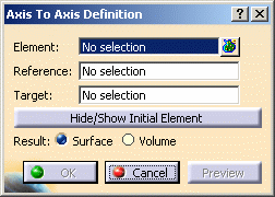
Select the Element to be transformed into a new axis system. This option is available only in the Generative Shape Design workbench.
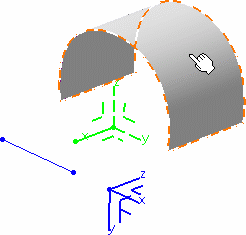
-
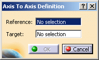
Select the initial (Reference) axis system.

-
Select the Target axis system, that is, the one into the element should be positioned.
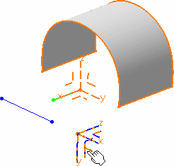
-
Click OK to create the transformed element.
The new geometry is now positioned into the new axis system. 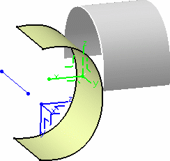
The element (identified as Axis To axis transformation.xxx) is added to the specification tree. 
- Click Hide/Show initial element to hide or show the original element for the translation. This option is available only in the Generative Shape Design workbench.
- You can select an axis system as the
Element to be transformed, providing it was previously
created.
The element is identified as Axis To axis transformation.xxx in the specification tree, however the associated icon is the axis system's .
. - Choose whether you want the result of
the transformation to be a surface or a volume by switching to
either Surface or Volume option. This option
is available only in the Generative Shape Design workbench.
This switch only concerns volumes since the transformation of a surface can only be a surface. Thus in case of multi-selection of volumes and surfaces, the switch only affects volumes.
Note:- Replacing an input element does not change the result type,
- The switch between surface and volume is grayed out when
editing the feature.
This capability is only available with Generative Shape Optimizer. To have further information about volumes, refer to the corresponding chapter.

- If you select a solid as the input element, the result will either be a surface or a volume.
- The selection of the feature prevails
over the selection of the sub-element.
To select a sub-element, you need to apply the ''Geometrical Element'' filter in the User Selection Filter toolbar.
For further information, refer to the Selecting using a Filter chapter in the CATIA Infrastructure User's Guide.

The following capabilities are also available: Stacking Commands and Selecting Using Multi-Output.
![]()
