This may be useful when, in a complex part, a branch of the part should not be affected by an update, or is not updating correctly for instance.
This capability will let you work on the other elements present in the document while ignoring a specific element.
-
Right-click the element to be deactivated from the specification tree, and choose the xxx object > Deactivate contextual command.
-
Click OK.
The selected element as well as its children and aggregated elements (if any and depending on the selected options) are deactivated.
The ( ) symbol is displayed in the specification tree, and the corresponding geometry is hidden. Also refer to Symbols Reflecting an Incident in the Geometry Building.
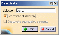
The selected element has no children nor aggregated elements
Other cases
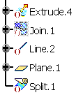
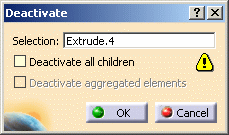
- The selected element has children but no aggregated elements
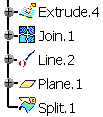
(for instance Extrude.4).

-
Deactivate all children is selected: it lets you deactivate the geometry based upon the element to be deactivated, that is dependent elements.
By default, the option is checked, except for modification features when a reroute is possible (see example below).
If you uncheck the option, a warning icon is displayed to inform you that there will be an update error.
-
Deactivate aggregated elements is disabled.
-
![]()
- The selected element has aggregated elements but no children
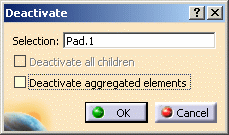
(for instance a Part Design feature based on a sketch, such as Pad.1).
Open the Deactivate2.CATPart document.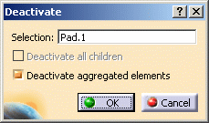

- Deactivate all children is disabled.
-
Deactivate aggregated elements is selected: it lets you deactivate the geometry aggregated below the element to be deactivated.
Whenever you deactivate a feature, you can choose between deactivating the corresponding aggregated element (element located just below the feature based on it, in the specification tree) or not (as shown below):
When deactivating a Boolean operation, by default all operated bodies (located below the Boolean operation node) are deactivated too: just deselect Deactivate aggregated elements if you wish to keep the bodies.
![]()
-
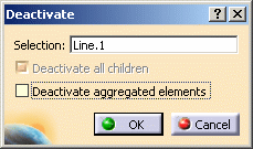
The selected element has children and aggregated elements (for instance Line.1).
Open the Deactivate3.CATPart document.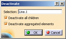

-
Both Deactivate all children and Deactivate aggregated elements options are selected.
If you uncheck Deactivate aggregated elements, Deactivate all children is automatically disabled. Indeed, the aggregated elements have children unlike Line.1.
-
-
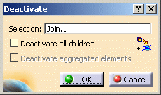
The selected element is a modification feature, has children and a reroute is possible (for instance Join.1).
You can check Deactivate all children to avoid rerouting the element. All children are deactivated.
When no reroute is possible, Deactivate all children is checked.
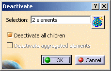
In case of multi-selection, the number of elements is displayed in the Selection field. You can click to display the list of elements.
- Copy mode: the deactivation is performed on the modification
operation of the feature (providing a modification of a feature of same
dimension). When deactivated, the result of the
feature is identical to its main input (that is the modified element) and
thus can be selected and highlighted.
Here are the features concerned by this mode:- Projection
- Curve Smooth
- Blend (with Trim option only)
- Corner (with Trim option only)
- Shape Fillet (with Trim option only)
- Connect Curve (with Trim option only)
- Parallel Curve
- Offset
- Variable Offset
- Rough Offset
- 3D Curve Offset
- Split (on Element to cut)
- Trim (on Trimmed Elements)
- All transformations in creation and modification modes
- Sweep (tangent sweeps with Trim option)
- Surface Extrapolation (with Assemble Result option only)
- Curve Extrapolation (with Assemble Result option only)
- Join (copy of the first element)
- Healing (copy of the first element)
- Combine
- Invert
- Near
- Develop
- Wrap Curve
- Wrap Surface
- Bump
- Shape Morphing
- Diabolo
- Destructive mode: the deactivation makes the feature unusable.
When selected, the feature cannot be seen in the 3D geometry.
Here are the features concerned by this mode:- Line
- Plane
- Circle
- Reflect Line
- Spiral
- Spline
- Helix
- Intersection
- Extrude
- Revolution
- Cylinder
- Sweep (except tangent sweeps with trim option)
- Multi-Sections Surface
- When elements are imported using multi-part links (external references) or using a Copy-Paste As result with link, the deactivation concerns the link, not the feature. As a consequence, the feature can still be selected.
- To re-activate the elements, right-click their name in the specification tree and choose the XXX object > Activate contextual command.
- It is not possible to deactivate datum elements as they do not have an history. Indeed, a deactivation would destroy their geometry and a reactivation would therefore be impossible.
- When the activation of a geometrical feature is already piloted by a knowledge formula, it is not possible to activate or deactivate it using the standard contextual command.
![]()
