Multi-Axis
Helix Machining
The information in this section will help you create and edit Multi-Axis
Helix Machining operations in your manufacturing program.
Click the
 icon, then select the geometry to be machined
 .
A number of collision checking parameters can be
set on the Geometry tab page.
A number of strategy parameters
 are available for defining:
Specify the tool to be used
 ,
feeds and speeds
 ,
and NC macros
 as needed.
For more information about how to specify this type of operation please refer
to:
Multi-Axis Helix Machining: Strategy Parameters
Multi-Axis Helix Machining: Machining Parameters
|
|
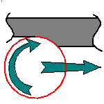
Direction of cut
Specifies how machining is to be done. |
- In Climb milling, the front of the advancing
tool (in the machining direction) cuts into the material
first.
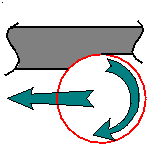
- In Conventional, the rear of the advancing tool
(in the machining direction) cuts into the material first.
|
|
|
Machining tolerance
Specifies the maximum allowed distance between the theoretical
and computed tool path. |
|
|
Maximum discretization step
Defines the maximum allowed distance between two points
on the tool path. It is used to ensure linearity between points
that are far apart. Default value is 100 m. |
|
|
Maximum discretization angle
Specifies the maximum angular change of tool axis between
tool positions. It is used to add more tool positions (points
and axis) if value is exceeded. Default value is 180 degrees. |
|
|
Note: The Maximum discretization step and Maximum discretization
angle influence the number of points on the tool path. The values
should be chosen carefully if you want to avoid having a high
concentration of points along the tool trajectory.
These parameters also apply to macro paths that are defined
in machining feedrate. They do not apply to macro paths that
do not have machining feedrate (RAPID, Approach, Retract, User,
and so on). |
Multi-Axis Helix Machining: Radial Parameters
|
|
Stepover
Defines the criteria to be used for distributing the turns
of the generated helix: by scallop height, distance between
turns, or number of turns.
Note that the machining tolerance influences the distance
between two consecutive turns.
For example, when the machining tolerance value is
increased, the distance between two consecutive turns is
decreased according to the specified scallop height value. |
|
|
Scallop height
Specifies the maximum scallop height between consecutive
turns of the generated helix in the radial strategy. |
|
|
Distance between turns
Defines the maximum distance between consecutive turns of
the generated helix in the radial strategy. |
|
|
Number of turns
Defines the number of turns of the generated helix in the
radial strategy. |
|
|
Skip path
Gives the possibility of not machining the path on
the first contour, the path on the last contour, or both these
paths. |
Multi-Axis Helix Machining: Tool Axis Parameters
|
|
Tool axis mode
Specifies how the tool axis is to be guided:
Lead and Tilt,
4-axis Tilt or
Interpolation.
Lead and Tilt
In this mode the tool axis is normal to the part surface
with respect to a given lead angle (a) in the forward tool motion
and with respect to a given tilt angle (B) in the perpendicular
direction to this forward motion.
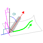
There are several types of lead and tilt modes as follows:
- Fixed lead and tilt: Here both the lead and tilt
angles are constant.
- Variable lead and fixed tilt: Here the tool axis
is allowed to move from the specified lead angle within
a specified range, the tilt angle remaining constant.
- Fixed lead and variable tilt: Here the tool axis
is allowed to move from the specified tilt angle within
a specified range, the lead angle remaining constant.
Lead angle
Specifies a user-defined incline of the tool axis in a plane
defined by the direction of motion and the normal to the part
surface. The lead angle is with respect to the part surface
normal.
Maximum lead angle
Specifies a maximum lead angle.
Minimum lead angle
Specifies a minimum lead angle.
Tilt angle
Specifies a user-defined incline of the tool axis in a plane
normal to the direction of motion. The tilt angle is with respect
to the part surface normal.
Allowed tilt
Specifies the range of allowed tilt variation.
4-axis Tilt
The tool axis is normal to the part surface with respect
to a given tilt angle and is constrained to a specified plane.
This mode has the same behavior as Lead and Tilt except that
the local normal to the part is replaced by a normal to plane
constraint. You can specify a Lead Angle and a Tilt
angle.
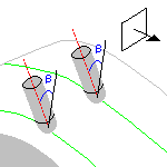
For example, this mode is dedicated to milling parts with
tool axis nearly parallel to the part itself (near flank milling).
It is primary intended for NC machines whose configuration is
A+C, but it can be used on any other multi-axis machine.
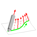
Interpolation
In this mode the tool axis is interpolated between selected
axes. Four default interpolation axes are proposed initially.
The orientation of these axes can be adjusted by the user. Additional
axes can be inserted anywhere on the area to machine to ensure
that the tool can be positioned at each point on the trajectory
and that the trajectory is collision-free.
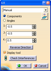
The orientation of an axis is
adjusted by means of the Axis Definition dialog box.
- Manual. Choose one of the following:
- Components to define the orientation
by means of I, J and K components.
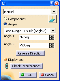
- Angles to define the orientation by means
of a rotation of the X, Y or Z axis. The rotation is
specified by means of one or two angles.
-
|
Multi-Axis Helix Machining: Cutter Compensation Parameters
In the
Machine Editor, the Compensation tab contains options for:
- globally defining the 3D contact cutter compensation mode: None/Contact/Tip
and Contact
- imposing the compensation mode to all operations supporting the selected
mode whatever the choice defined at machining operation level.
If the options are set as follows, compensation can be managed at machining
operation level.

In this case a Compensation tab appears in the Strategy page of the machining
operation editor, and the following options are available.
Compensation output
Allows you to manage the generation of Cutter compensation (CUTCOM)
instructions in the NC data output:The following options
are proposed:
3D Contact (G29/CAT3Dxx)
The tool contact point will be visualized during tool path
replay. Cutter compensation instructions are automatically generated
in the NC data output. An approach macro must be defined to
allow the compensation to be applied.
Example of generated APT source:
$$ Start generation of : Multi-Axis Helix Machining.1

							FEDRAT/ 1000.0000,MMPM

							SPINDL/ 70.0000,RPM,CLW

							CUTCOM/NORMPS

							$$ START CUTCOM NORMPS XC, YC, ZC, XN, YN, ZN, I, J,
							K

							.../...

							CUTCOM/OFF

							$$ END CUTCOM NORMPS XC, YC, ZC, XN, YN, ZN, I, J, K

							$$ End of generation of : Multi-Axis Helix Machining.1
None
Cutter compensation instructions are not automatically generated
in the NC data output. However, CUTCOM instructions can be inserted
manually. For more information, please refer to
How to generate CUTCOM syntaxes.
|
Multi-Axis Helix Machining: Geometry
You can specify the following Geometry:
- Part elements (faces) with possible Offset on Part.
Faces must be continuous in tangency in order to ensure good quality tool
paths.
- Four limiting curves comprising:
- Upper and lower contours, which must be closed contours. The selected
curves must lie on faces.
- Leading and trailing edges, which must intersect the upper and lower
contours. The selected curves must lie on faces.
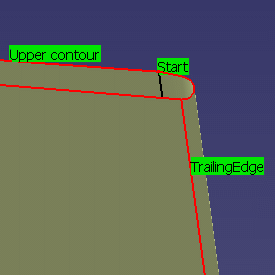
- A Start or a Stop point, which specifies the entry or the exit point
of the helix. When one point is selected, the other point is automatically
deduced.
- Optionally, check elements with possible Offset on Check.
Multi-Axis Helix Machining: Collision Checking
This section shows how collision checking is managed in Multi-axis Helix
Machining operations. The Collision Checking parameters are accessed in the
Geometry tab page of the operation's dialog box.
Collision checking can be performed on check and part elements with the tool
assembly (that is, the complete shape of the cutter plus its holder) or the
cutting part of the tool (red part of following tools):
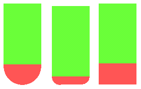
To save computation time, you should use the tool assembly only if the geometry
to be checked can interfere with the upper part of the cutter.
Collisions with Check Elements
The parameters involved for check elements (such as fixtures) are described
below.
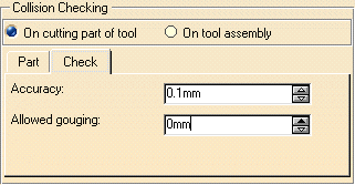
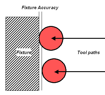
Check (or Fixture) accuracy
Defines the maximum error to be accepted with respect to the fixture with
its offset. Setting this parameter to a correct value avoids spending too much
computation time to achieve unnecessary precision.
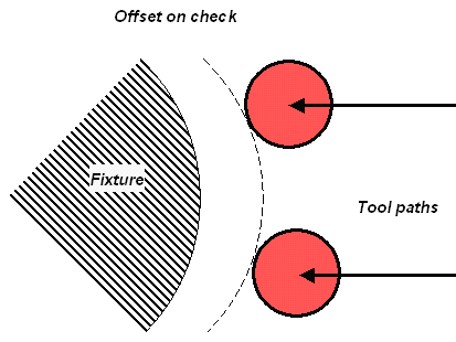
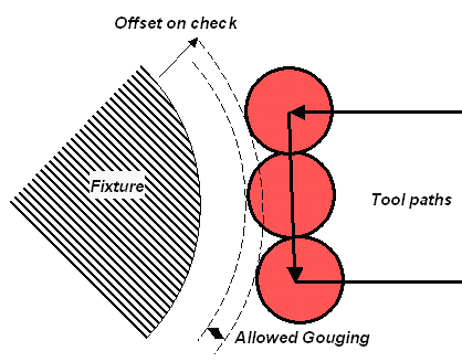
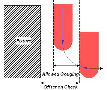
Offset on check
Defines the minimum distance between the cutter and the fixture, used to limit
the tool path.
Allowed gouging
Defines the maximum cutter interference with the fixture during "linking passes"
(including approach and retract motion).
The illustration below shows return motion with no macro or jump.
The illustration below shows
return motion with macro between path and fixture.
Collisions with Part Elements
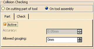
To activate collision
checking on part elements, you must select the Active checkbox.
Part
accuracy
Defines the maximum error to be accepted with respect to the part with
its offset. This parameter is set to the machining tolerance value. It can be
only be changed by modifying the machining tolerance.
Allowed gouging
Defines the maximum cutter interference with the part during "linking passes"
(including approach and retract motion).
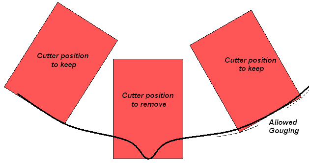
In Multi-axis Helix Machining, collision checking with part elements is useful
in the following case.
Concave and non smooth part milled with 0 degree Lead angle
Note that Allowed gouging must be set to a non zero value, otherwise
a "Nothing to Mill" message may be issued.
In Multi-axis Helix Machining, collision checking on part elements is
not useful in the following cases.
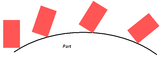
Convex part machined with ball, flat or filleted ended tool or with a Fixed
or Variable tool axis mode.
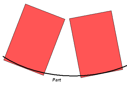
Concave part milled with 0 degree Lead angle.
A "Nothing to Mill" message may be issued.
Multi-Axis Helix Machining: Tools
Recommended tools for Multi-Axis Helix Machining are End Mills, Face Mills,
Conical Mills and T-Slotters.
Multi-Axis Helix Machining: Feeds and Speeds
In the Feeds and Speeds tab page, you can specify feedrates for approach,
retract and machining as well as a machining spindle speed.
Feedrates and spindle speed can be defined in linear or angular units.
A Spindle output checkbox is available for managing output the SPINDL instruction
in the generated NC data file. If the checkbox is selected, the instruction
is generated. Otherwise, it is not generated.
Feeds and speeds of the operation can be updated automatically according
to tooling data and the Rough or Finish quality of the operation. This is described
in
Update of Feeds and Speeds on Machining Operation.
Multi-Axis Helix Machining: NC Macros
You can define transition paths in your machining operations by means of
NC Macros. These transition paths are useful for providing approach, retract
and linking motion in the tool path.
An Approach macro is used to approach the operation start point.
A Retract macro is used to retract from the operation end point.
A Linking macro may be used in various cases (for
example, to link two non consecutive paths).
A Clearance macro can be used in a machining operation to avoid a fixture,
for example.
![]() icon, then select the geometry to be machined
icon, then select the geometry to be machined
![]() .
A number of collision checking parameters can be
set on the Geometry tab page.
.
A number of collision checking parameters can be
set on the Geometry tab page.![]() are available for defining:
are available for defining:![]() ,
feeds and speeds
,
feeds and speeds
![]() ,
and NC macros
,
and NC macros
![]() as needed.
as needed.


