The following procedure explains how to produce a collision-free tool path when you use Multi-Axis Helix Machining in Interpolation mode. In this example, it describes an iterative process for machining a blisk blade while avoiding collisions with neighboring blades.
The stages of this procedure are:

A user scenario of this procedure is provided in the section Create a Multi-Axis Helix Machining Operation in Interpolation Mode. More information about Multi-Axis Helix Machining is provided in the Reference section.
In the Geometry tab of the machining operation editor, define the necessary geometry:
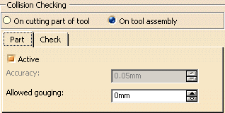
However, at this stage do not select any check elements and make sure that the collision checking option is deactivated in the Part tab.
In the Tool tab of the machining operation editor, select an appropriate tool for the geometry to be machined (for example, a conical ball-ended mill tool).
In the Strategy tab of the machining operation editor, set the tool axis mode to Interpolation and set the other parameters (number of turns, and so on).
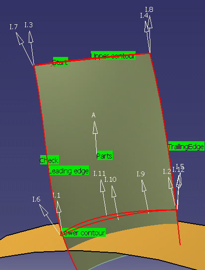
Four interpolation axes are proposed by default at the following intersection points:
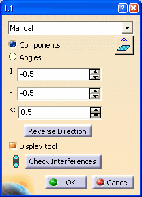
You can adjust the orientation of each of the default axes.

Replay the tool path to verify that the tool can be positioned at each point on the trajectory. If the tool cannot be positioned at each point on the trajectory, you may need to adjust the default axes and/or insert additional interpolation axes. You can insert any number additional axes on the faces of the blade.
Note that interpolation axes are applied at contact points on the trajectory. The application point of an interpolation axis must be on a selected face. If the point is not on a selected face, it will be projected onto the part. This may give undesirable results. Remember also that points created on the fly are not associative, so it is best to avoid creating points in this way.
You may need to adjust the orientation of the additional axes.
Replay the tool path to verify that the tool can be positioned at each point
on the trajectory.
The collision checking options are deactivated in the Geometry tab of the
machining operation editor, so this replay is done with no collision check.
If the tool cannot be positioned at each point on the trajectory, adjust the
interpolation axes until this criteria is satisfied.
If the tool can be positioned at each point on the trajectory, you can move
onto the next stage: collision checking with the part.
Activate collision checking between the part and the tool assembly in the Geometry tab of the machining operation editor.

Replay the tool path to check for collisions. At this stage, since there are no selected check elements, collision checking is on the part elements only.
If there are collisions detected with the part, adjust the interpolation
axes until the tool path is collision free.
If there are no collisions, you can move onto the next stage: collision
checking with neighboring blades.
In the Geometry tab of the machining operation editor select check elements as follows:
Replay the tool path to check for collisions. Now, the program checks for collisions between the tool assembly and the part and check elements.
If there are collisions detected, adjust the interpolation axes until the
tool path is collision free.
If there are no collisions, you can save the Multi-Axis Helix Machining
operation.
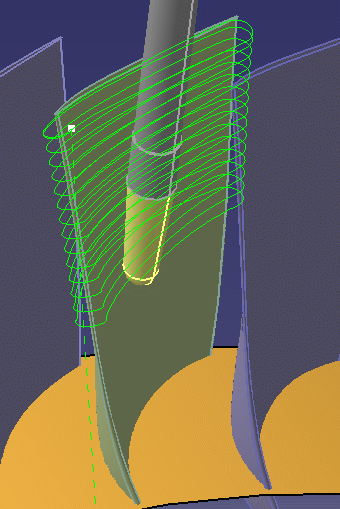
The left-hand figure below show an example of the default and additional interpolation axes necessary to obtain the collision-free trajectory illustrated in the right-hand figure.
 |
 |