|
|
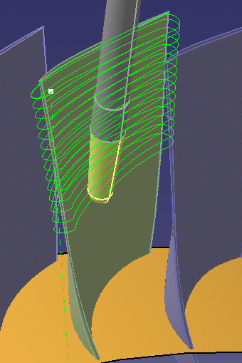
This task illustrates how to insert a
Multi-Axis Helix Machining operation
in the program. This operation will be used to generate
a single helix toolpath to mill a
blisk blade, while avoiding
collisions with neighboring blades. The scenario below show how to quickly create an operation. The recommended procedure is described in Collision-Free Multi-Axis Helix Machining in the Methodology section. To create the operation you must define:
|
||||||||||||||||||||||||||||||||||||||||
|
|
Open the Blisk.CATPart
document, then select Machining > Advanced Machining
from the Start menu. Make the Manufacturing Program
current in the specification tree.
The following procedure describes how to machine the middle (green) blade with no tool collisions with the two neighboring blades. |
||||||||||||||||||||||||||||||||||||||||
|
|
1. |
Select the Multi-Axis Helix Machining icon
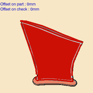
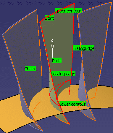
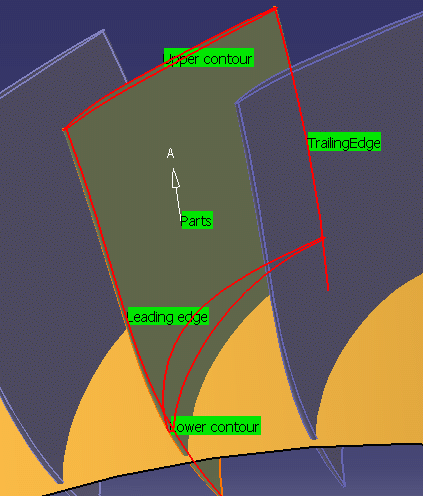
The part surface, upper and lower contours, and leading and trailing edges of the sensitive icon are colored red indicating that this geometry is required and must be selected. The upper and lower contours and the leading and trailing edges must lie on the faces selected as part surface. Selection of check elements (such as neighboring blades or fixtures) is optional. |
|||||||||||||||||||||||||||||||||||||||
| 2. |
Click the red part surface in the icon then select the faces
to be machined in the 3D window. In this scenario, you must
select 4 faces: the front face, the back face, the leading
face, and the trailing face. The Face Selection toolbar appears to help you select these faces. Note that faces must be continuous. Gaps between faces may result in a bad tool path. |
||||||||||||||||||||||||||||||||||||||||
| 3. | Select the upper and lower contours. The Edge Selection toolbar appears to help you select these contours. They must be closed contours. | ||||||||||||||||||||||||||||||||||||||||
| 4. | Select the leading and trailing edges to define the limits of the machining. The Edge Selection toolbar appears to help you select these edges. They must intersect the upper and lower contours. | ||||||||||||||||||||||||||||||||||||||||
 |
|||||||||||||||||||||||||||||||||||||||||
|
|
|
||||||||||||||||||||||||||||||||||||||||
| 5. |
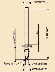
A tool is proposed by default when you want to create a
machining operation. If the proposed tool is not suitable,
just select the Tool tab page
Please refer to Edit the Tool of an Operation for more information. |
||||||||||||||||||||||||||||||||||||||||
| 6. |
Select the Strategy tab page
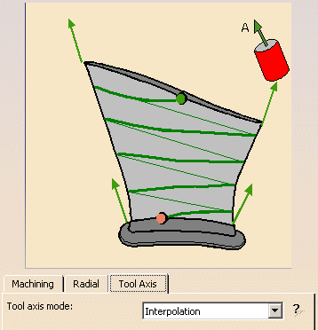
Set the Tool axis mode
to Interpolation.
|
||||||||||||||||||||||||||||||||||||||||
| 7. |
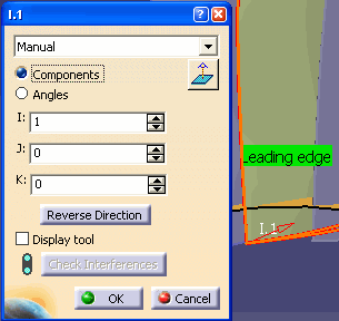
Click one of the interpolation
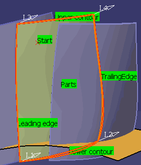
axis symbols in the sensitive icon. Default Interpolation axes (I.1 to I.4) are displayed at the four corners of the part.
General information about this dialog box is available in the Reference section. Click OK in the dialog boxes when the interpolation axes are defined. |
||||||||||||||||||||||||||||||||||||||||
| 8. |
Set the Machining
parameters, for example:
|
||||||||||||||||||||||||||||||||||||||||
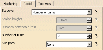
| 9. |
Set the Radial parameters,
for example:
|
||||||||||||||||||||||||||||||||||||||||
| 10. |
Replay the tool path to verify that the tool can be
positioned at each point on the trajectory. If the tool cannot be positioned at each point on the trajectory, adjust the default interpolation axes and possibly insert additional interpolation axes until this criteria is satisfied. You can add an additional axis by clicking one of the interpolation axis symbols in the Strategy tab page then either selecting an existing point on the part or selecting anywhere on the part. You can delete an additional axis by right-clicking it
and selecting the Remove contextual command.
Note that interpolation axes are applied at contact points on the trajectory. The application point of an interpolation axis must be on a selected face. If the point is not on a selected face, it will be projected onto the part. This may give undesirable results. Once the tool can be positioned at each point on the trajectory, you can set the collision checking option on the Geometry tab page. |
||||||||||||||||||||||||||||||||||||||||
| 11. |
If there are collisions detected, adjust the interpolation
axes until the tool path is collision free. Once there are no collisions, you can select the faces of neighboring blades as check surfaces.
You can then replay the tool path to check for collisions with the selected faces.
|
||||||||||||||||||||||||||||||||||||||||
| 12. |
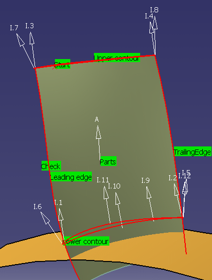
You may need to adjust the interpolation axes and possibly
insert additional interpolation axes until the tool path
is collision free. The following figure shows an example of the default and additional interpolation axes that will give a collision-free trajectory.
|
||||||||||||||||||||||||||||||||||||||||
|
|
The corresponding data is as follows:
|
||||||||||||||||||||||||||||||||||||||||
| 13. |
The tool path can be replayed and checked for collisions.
|
||||||||||||||||||||||||||||||||||||||||
| 14. | Click OK to create the operation. | ||||||||||||||||||||||||||||||||||||||||
|
|
|
||||||||||||||||||||||||||||||||||||||||
|
|
|||||||||||||||||||||||||||||||||||||||||

