- By clicking a
Default machine icon
 :
:
- 3-axis machine
- 3-axis machine with rotary table
- 5-axis machine
- horizontal lathe machine
- vertical lathe machine
- multi-slide lathe machine (refer to Multi-Slide Lathe Machining User's Guide for more information about this machine).
Note: Instead of using a default horizontal or vertical lathe machine, you are recommended to use a multi-slide lathe machine restricted to one spindle and one turret.
- By clicking Assign
a Machine by File Selection
 then selecting a Generic machine:
A generic machine is a CATProduct representation that was created using the NC Machine Tool Builder product. Available machine types are:
- 3-axis machine with no rotary axis
- 3-axis machine with 1 rotary axis on table
- 3-axis machine with 2 rotary axes on table
- 3-axis machine with 1 rotary axis on table and 1 rotary axis on head
- 3-axis machine with 1 rotary axis on head
- 3-axis machine with 2 rotary axes on head
- 5-axis continuous machine (without generation of ROTABL or ROTHEAD instruction)
Each machine contains all the necessary NC parameters and kinematic definition data for the Part Operation.
A number of sample generic machines are provided at this location:
..\OS\startup\Manufacturing\Samples\NCMachineToollib\DEVICES.
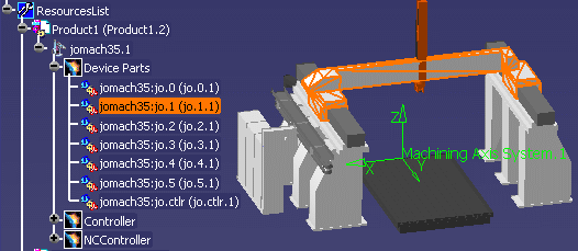
- By clicking Assign a Machine
by ResourceList Selection
 to select a Generic machine directly from the PPR tree:
Only machines created using NC Machine Tool Builder can be selected in the ResourceList. Default machines cannot be selected in this way.
Machine Name and Comment
If needed, enter a new name for the machine and assign comments to it.
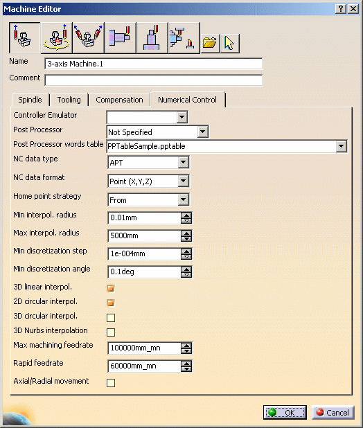
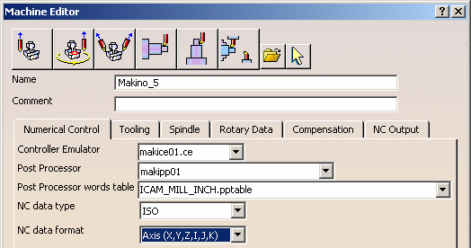
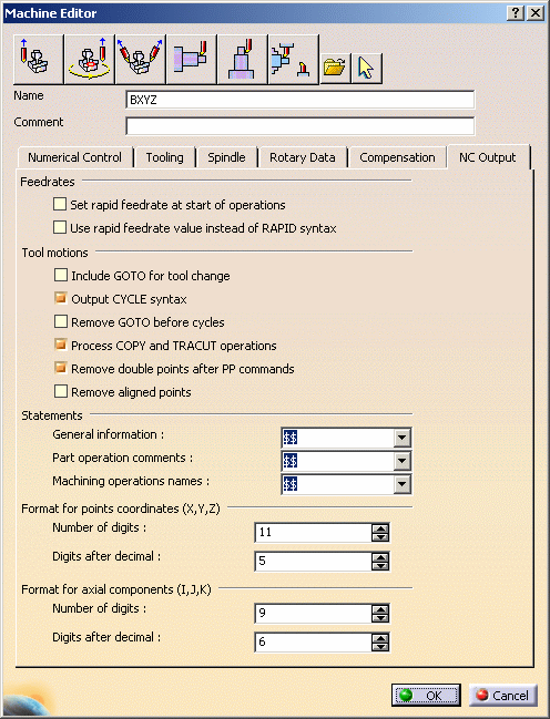
Numerical Control Tab
You can also specify the following.
- Controller Emulator and Post Processor: Note that a Controller Emulator/Post Processor vendor must be set in the Tools > Options > Machining > Output tab.
- Post Processor words table: Sample PP word tables are delivered with the product in the ..\startup\manufacturing\PPTables folder.
- NC data type: Defines whether APT, Clfile or NC code is the preferred output type.
- NC data format: Defines whether tool point
coordinates (x,y,z) or tool point coordinates and tool axis
components (x,y,z,i,j,k) is the preferred output format.
- Home point strategyy: Defines whether a GOTO or FROM instruction is to be generated in the output APT source for the Home Point.
- Rapid feedrate: This is used to compute accurate machining time (in tool path replay and NC documentation, for example) and can be used to replace the RAPID instruction in the output APT source.
- Axial/radial movement: Defines whether axial/radial
transitions are to be used between the end of one operation
and the start of the next operation.
Note that a Rapid GOTO statement is added for the axial-radial movement if the option is selected.
![]()
- Min and Max interpolation radius
values are defined for generating circular interpolation
in NC data output. These parameters are used in tool path
computation and output file generation.
You should check and possibly modify these values before creating machining operations. Otherwise, correct circular interpolation may not appear in the NC data output.
Please note that if an interpolation value is modified after machining operation creation and tool path generation, tool paths should be recomputed (right-click Program and select Compute Tool Path in Force computation mode) before generating the output file. - 3D Nurbs Interpolation:
specifies the ability to generate NURBS data in an APT output file.
Tooling Tabb
Displays tooling parameters including the Tools catalog.
Spindle Tab
Displays spindle parameters.
Turret Tab
Displays turret parameters for vertical and multi-axis lathe machines.
Rotary Table or Rotary Data Tab
For 3-axis machine with rotary table, rotary table parameters are displayed.
For machines with more than one rotary axis on head or table, parameters are displayed for each axis.
The rotary axis name can be set on a generic machine in NC Machine Tool Builder. This allows a better coverage of machines for automatic generation of transition paths (for example, when the rotary axis of the machine is not parallel to the X, Y or Z axis of the absolute axis system).
Compensation
Cutter compensation options are displayed for 3D contact compensation.
Contact and Tip & Contact compensation modes can no longer be globally applied to all operations supporting this 3D Cutter compensation.
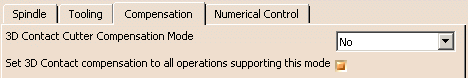
If the Contact or the Tip & Contact option
is selected and the check box is not selected (see example below),
a Compensation tab appears in the Strategy page of the machining
operation editor.

In this case, 3D contact compensation can be managed at machining
operation level.
Please note that some machining operations propose cutter compensation
modes other than 3D contact (2D radial profile, for example).
NC Output
For generic machines created using the NC Machine Tool Builder product, the Machine Editor centralizes all NC output options. If such a machine is defined on the Part Operation, all options for NC data generation can be read automatically from the machine definition.
The Resource List is updated with selected machine.
In this case the machine appears directly in the 3D viewer. It is possible to use the Hide/Show contextual command on the machine nodes in the tree to hide all or part of the machine.
Machining Operations Supporting Cutter Compensation
The following table specifies the Compensation output modes available for each operation. Cutter compensation instructions are generated on the NC data output depending on the selected mode as follows:
- 2D radial tip
Compensation is computed in a plane normal to the tool axis, and activated with regard to a cutter side (left or right).
The radius that is compensated is the cutter radius.
Output is the tool tip point (XT). - 2D radial profile
Compensation is computed in a plane normal to the tool axis, and activated with regard to a cutter side (left or right).
The radius that is compensated is the cutter radius.
Output is the tool profile point (XP). - 3D radial
Compensation is computed along a 3D vector (PQR), normal to the drive surface, in contact with the flank of the tool.
The radius that is compensated is the cutter radius.
Output is the tool tip point (XT) and PQR vector. Tool axis vector (IJK) is output in multi-axis. - 3D contact
Compensation is computed along a 3D vector (XN), normal to the part surface, in contact with the end of the tool.
The radius that is compensated is the corner radius.
Output is the contact point (XC) and XN vector.
The tool tip point (XT) may also be given if this choice is set on the machine.
Tool axis vector (IJK) is output in multi-axis.
| Machining Operation | 2D radial tip | 2D radial profile | 3D radial | 3D contact |
| Profile Contouring (between planes) | Yes | Yes | - | - |
| Pocketing | Yes | Yes | - | - |
| Circular Milling | Yes | Yes | - | - |
| Sweeping | - | - | - | Yes |
| Contour Driven | - | - | - | - |
| Spiral Milling | - | - | - | - |
| Z Level | - | - | - | Yes |
| Sweep Roughing | - | - | - | - |
| Isoparametric Machining | - | - | - | Yes |
| Multi Axis Sweeping | - | - | - | Yes |
| Multi Axis Curve (Contact) | - | - | - | Yes |
| Multi Axis Contour Driven | - | - | - | Yes |
| Multi Axis Helix Machining | - | - | - | Yes |
| Multi Axis Flank Contouring | - | Yes | Yes | - |
Machining Operations Supporting Circular Interpolation
Machining operations supporting circular interpolation are as follows:
- Roughing, Cavities Roughing, Multi-Pockets Machining: only when strategy is set to Spiral, Concentric, Helical, or Offset from Part
- Zlevel: only for circular macros
- Facing, Pocketing, Profile Contouring, Curve Following, and Groove Milling
- Circular Milling, Thread Milling (for circular macros), and T-Slotting
- Multi-Axis Curve Machining
- circular macros of all machining operations but only for planar trajectories
- Rough Turning, Groove Turning, Recess Turning, Profile Finishing, Groove Finishing, Ramp Roughing, and Ramp Recessing.
![]()