Open the ABF_AllTypeFast_02.CATProduct document.
-
Click either BiW Weld Series Annotations
 or BiW Weld Fastener Annotations
 from BiW Annotations toolbar.
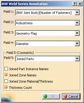
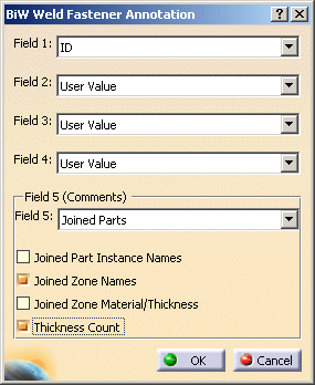
The BiW Weld Series Annotation or BiW Weld Fastener Annotation dialog box is displayed. You can notice that both dialog boxes are similar: 

-
Select a parameter in each field.
Annotations attributes are displayed according to the ABF standard.
All fields can be customized, except for the F5 Field. This field is used to display only user or joined part information.
Use the most recent standard to get the parameterization of the functional annotations. If you use a former standard, fields are not valuated and are set to User Value.Field 5: information frame - Joined Parts
You can choose to display:- Joined Part Instance Names
- Joined Zone Names
- Joined Zone Material/Thickness
- Thickness Count
- Process Type (in this case all parameters above said are unavailable)
- Process Type [Robustness] (that is Process Type and Robustness) (in this case all parameters above said are unavailable)
- User Value (in this case all parameters above said are unavailable)

For further information about these options, refer to Displaying Joined Parts Information in a Balloon. - Joined Parts
-
Point out a fastener in the 3D geometry or in the specification tree, for instance Joint Element.1.
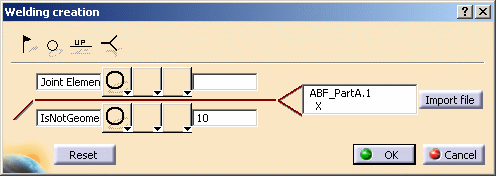
The Welding creation dialog box is displayed. Here is the example with a fastener annotation: 
The dialog box updates as you fill in the fields. You can select the symbols of your choice from the combo lists: they are not associated with the Process Type. -
Click OK to create the annotation.
- Annotations are created in the view plane: if there is no activated annotation plane during the creation, an annotation plane is automatically created parallel to the xy plane.
- They are positioned according to the fastener type: at the location point for a spot or along the curve for a curve bead.
- They can be attached to any type of fasteners but they are always visualized under the Welds node in the specification tree.
- They are associative with their attached fastener.
- If the engineering class parameter of a fastener is set to U (for Unspecified Value), the field corresponding to the associated annotation will not display any value.
- Encoded values are displayed through the annotation, not translated values. For instance, the encoded values are Process Type = 21 and Robustness = C.
If the annotation is associated to a spot point whose process category is set to Welding and process type to Resistance, the symbol is automatically valuated. The display of the symbol depends on the standard defined in Tools > Options > Mechanical Design > Functional Tolerancing & Annotations, Tolerancing tab:
for JIS standard and
for any other standard.
The annotation symbol is not associative with the others process types; for example, if the process category or the process type of the welding resistance spot point is modified (say changed into an adhesive spot point), the symbol of the associated annotation is not modified i.e. remainsor
.
If a field is associated to a fastener parameter (that is different from "User Value"), you are advised not to manually modify it. Indeed, this field will be associative with the fastener parameter. Nevertheless, if you modify by mistake this field value, when
clicking OK at the creation of the annotation or at the next update,
the former associated values will be automatically restored.
Modifying and Editing a Functional Annotation
- Functional annotations (except for datum associations) are
associative with their attached fasteners:
- if you modify the fastener's location or attributes (joined parts, ID, process type, etc.) and the update the product, the annotation is automatically re-positioned and updated.
- if you delete the fastener and update the product, the attached annotation is automatically deleted.
-
if you select the fastener, all associated annotations are highlighted both in the 3D area and in the specification tree, providing 3D-Annotation-Query switch On/Switch Off
 is activated.
For further information, refer to Querying 3D Annotations in the 3D Functional Tolerancing & Annotation User's Guide.
- You can modify an annotation either by:
- changing its position:
- transferring it into another annotation plane
- moving it through drag and drop
-
mirroring
-
deleting it
-
editing its parameters
-
associative annotations: all the fields can be modified. However, if you modify by mistake a value set to an ABF attribute, the correct value is automatically restored once you update or check the corresponding fastener.
-
datum annotations: all the fields can be modified.
-
both annotation types: symbols can be modified
The symbol is automatically updated if you modify a fastener's process category and type to Welding Resistance. However, it remains the same if you modify a Welding Resistance fastener to any other process category and type.
-
-
modifying the visualization plane of the annotation text
- changing its position:
- You cannot move an annotation independently from its annotation plane.
Creating a Datum Annotation
- Datum annotations are not associative with their attached fasteners: if you modify a fastener's parameter (location, process category, process type, etc.) and update the product, it has no impact on the datum annotation.
- Datum annotations can be moved anywhere in the geometry area as it always remain in the annotation plane.
- They have a particular display in the specification tree:

![]()