Open the ABF_AllTypeFast_01.CATProduct document.
-
Click BiW Joined Parts Screen Report
 from the BiW Tools toolbar.
 -
Point out a fastener, a joint body or a joint in the 3D geometry or in the specification tree.
The BiW Joined Part Screen Report dialog box is displayed: 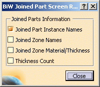
-
Select the joined parts information to be displayed:
-
Joined Part Instance Names: for fasteners, joint bodies and joints. Each name is displayed in a balloon in the order of the BiW Joint, each joined part is separated by the cross symbol X.
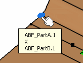
From a Fastener (3D geometry) 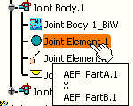
From a Fastener (specification tree) 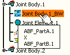
From a Joint Body (specification tree) 
From a Joint (specification tree) - Joined Zone Names: for fasteners and joint bodies. Each joined zone is displayed in a balloon in the order of the BiW Joint as follows: "Joined Part Instance Name / Zone Name". Each joined part is separated by the cross symbol X.

From a fastener (3D geometry) 
From a Fastener (specification tree) 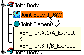
From a Joint Body (specification tree) - Joined Zone Material Thickness: for fasteners and joint bodies. Each name and thickness is displayed as follows: "Joined Zone Name (Material / Thickness)". Material and thickness are displayed between brackets and separated by a slash, material name and thickness of each joined zone name is separated by the cross symbol X.
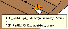
From a fastener (3D geometry) 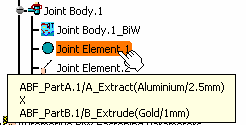
From a Fastener (specification tree) 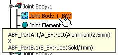
From a Joint Body (specification tree) - Thickness Count: for fasteners and joint bodies.
This parameter is optional. Each thickness count is displayed as
follows: "(Joined Part Number T)".
In our example, Joined Part Instance Names and Thickness Count are selected.
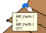
From a fastener (3D geometry) 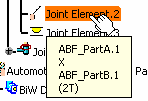
From a Fastener (specification tree) 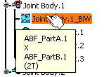
From a Joint Body (specification tree) -
The order of the joined parts in the balloon is the same as in the joint in the specification tree.
This command can be launched while in another command.
- The joined part numbers are not displayed.
- The first three parameters are exclusive, you can only select one at a time.
![]()