- a joint and a joint body are already created: click the desired icon and select the joint body in the selection tree.
- a joint and a joint body are already created: select the joint body in the selection tree and click the desired icon (here is the example used for our scenario).
- no joint body is created. Select the components or the publications, and click the desired icon: a joint and a joint body are created.
Make sure the spot point Fastener Type is set up in the standard file.
-
Select the joint body in the specification tree.
-
Click BiW Mechanical Point
 in the Mechanical BiW Fasteners
toolbar.
in the Mechanical BiW Fasteners
toolbar.The BiW SpotPoint Fastener Definition dialog box opens. 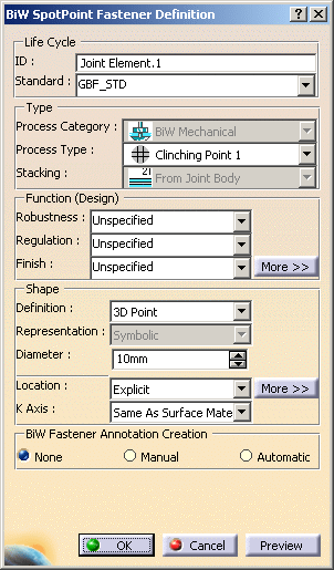
-
Specify whether you wish to use the existing standard or not.
If a standard has been imported, a spot point is created using this standard. If not, you are able to define your own values for each attribute. -
Define the following parameters of spot point:
-
In our example, select rivet as the Process Type.
Several shape definitions are available: shank, shank with head, shank with head and foot (see below). 
Hemisphere and Shanks definition are only available with Unspecified and Rivets process types. O = shank base plane offset from selection point L1 = head length
D1 = head diameterd = shank diameter (shape diameter)
l = shank lengthL2 = foot length
D2 = foot diameterDefault values:
D1 = D2 = dX2
L1 = L2 = d/3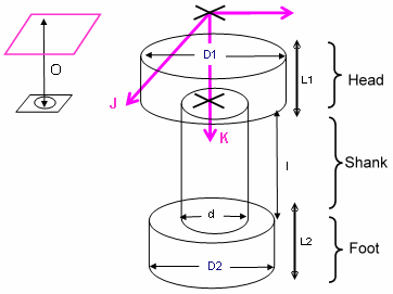
-
Define the shank diameter.
-
Define the spot point's location.

Selecting a circle to create a rivet automatically initializes the shank diameter. 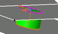

Rivets cannot apply on non planar circles. -
Define the K axis:
-
Same as Surface Material
-
Opposite to Surface Material
-
-
Click OK to create the spot point.
The spot point (identified as Joint Element.xxx) is added to the specification tree, under the Joint Body node. Defining the Shape of the Rivet
Shank
-
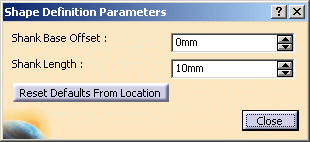
Define the Shank Base Offset.
-
Define the Shank Length.
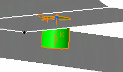
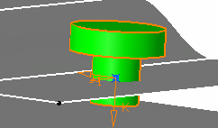
Shank with Head

-
Define the Shank Base Offset.
- Define the Shank Length.
- Define the Head Diameter.
- Define the Head Length.
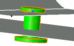
Shank with Head and Foot

-
Define the Shank Base Offset.
- Define the Shank Length.
- Define the Head Diameter.
- Define the Head Length.
- Define the Foot Diameter.
- Define the Foot Length.

- Reset Defaults From Location automatically resets the shank base offset and the shank length values according to the location of the spot point (computation of the crossed thicknesses), taking into account the gap between the crossed joined components.
- Reset Defaults From Diameter automatically resets the default diameter and length values of the head and foot.
-
![]()