|
-
Select the joint body in the specification tree.
-
Click BiW Welding SpotPoint
 from the Welding toolbar.
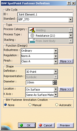
| The BiW SpotPoint Fastener Definition dialog box opens. |
 |
-
Specify whether you wish to use the existing standard
or not.
| If a standard has been
imported, a spot point is created using this standard. If not, you
are able to define your own values for each attribute. |
 |
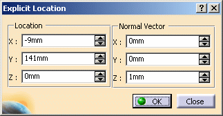
If the
last location method is different from Explicit, the ABF
application creates a specification part associated to the Assembly
Joint if this specification part does not already exist. |
 |
You must not delete this
specification part. |
-
Select the process type and the
stacking.
-
Define the design parameters:
-
Define the shape of the spot
point:
- Definition
- Representation
- Diameter
|
-
Select the location (see below):
|
|
| According to the location you choose, different dialog boxes
open, except when selecting the Explicit mode. |
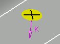
-
Define the orientation of the spot point by
setting the K axis to either:
-
Click OK
to create the spot point.
| The spot point (identified as Joint Element.xxx) is
added to the specification tree, under the Joint Body node. |
|
|
Note that:
- the selection of geometrical elements must be done within the
sub-components of the spot point's reference product, except when
using such options as Datum mode and Explicit locations.
- when selecting a geometric specification (curve or point), it
is recommended to select published elements in order to guaranty
associativity between elements.
- to authorize the selection of only published elements, check
the following option using Tools > Options > Infrastructure
> Part Infrastructure > General > Only use published elements for
external selection keeping links.
- when the On Surface and Explicit
methods are activated, the application will ignore the active
Part Infrastructure setting Only use published elements for
external selection and will enable the usage of non
published external geometry.
|
|
|
|
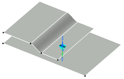
Locating the Spot Point
|
|
|
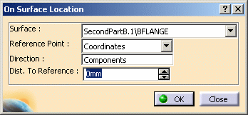
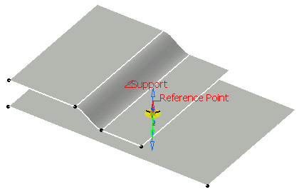
-
Select a
surface or a point to indicate the spot point location.
You can as well select a
circle instead of a point: the center of the circle is computed
to get the reference point.
The spot point will be created on the
selected zone, which may not be a support zone of the joint
body. |
-
(Optional)
Select a direction.
-
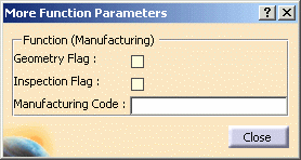
Click
More>> to:
|
|
|
-
Select a
point.
|
You can as well select a
circle instead of a point: the center of the circle is computed
to get the reference point. |
-
(optional)
Click More>> to:
-
modify
the reference point type (coordinates or axis origin)
-
modify
the distance to the reference point
-
modify
the normal vector if the reference point do not lie on the
surface.
|
|
|
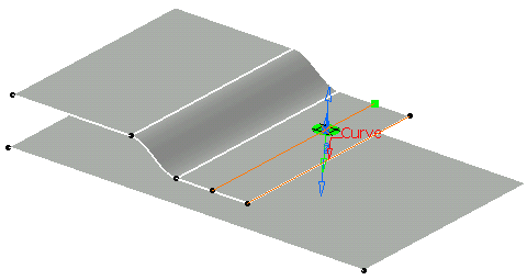
-
Select a
curve lying on a surface.
| Most of the times, a surface is selected by default. |
-
If needed,
select a surface.
|
|
You can select a published
surface from the drop-down list or choose No Selection if the
surface to be selected cannot be found and select the desired
surface in the 3D geometry. |
-
Modify the
offset.
-
Modify the
Reference Point (extremity or middle of the curve).
-
Modify the
distance to the reference point.
-
Define the
distance type (length or ratio)
For
instance, define 15mm as the offset, select the extremity as the
reference point and choose a distance of 30mm from the reference
point.
|
|
The Repeat
object after OK option appears in the BiW SpotPoint
Fastener Definition. Refer to the
Repeating Spots to create more spot points using the
currently created spot point as reference. |
|
|
|
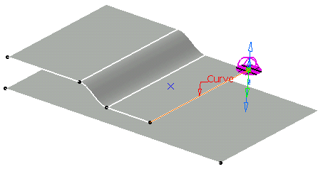
-
Select a
curve.
-
Select the
reference point (extremity or middle of the curve)
-
Modify the
distance to the reference point.
-
Define the
distance type (length or ratio)
-
Modify the
normal vector if the reference point does not lie on the surface.
|
|
Note that the last four
steps are optional. |
|
|
|
The
Repeat object after OK button appears in the BiW
SpotPoint Fastener Definition. Refer to the
Repeating Spots to create more spot
points using the currently created spot point as reference. |
|
|
|
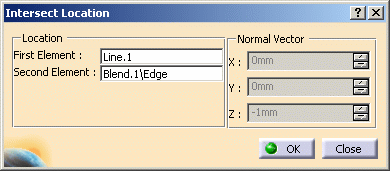
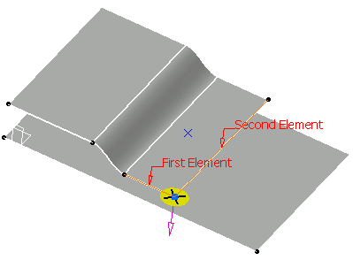
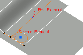
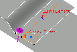
-
Select the
first and the second element.
| Elements can either be two curves or a curve and a surface. |
-
Click
More>> to optionally modify the normal vector if the
reference elements do not lie on a surface.
|
|
|
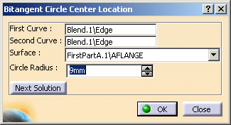
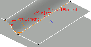
-
Select the
first and the second curves.
| They must not be parallel. |
-
Click
More>> to:
-
(optional) select a support surface in the drop-down list or in
the 3D geometry if the curves are not coplanar. In this case, the
center of gravity of the circle is
automatically computed.
-
define
the circle radius
-
(optional) modify the normal vector if the reference elements do
not lie on a surface.
|
|
|
|
- Select a surface or a point where the spot point is to be
created.
| You can as well
select a circle instead of a point: the center of the circle is
computed to get the reference point. |
-
(optional)
Click More>> to:
|
|