Note that this application incorporates intelligent design functions. This means that the application ensures your design meets a selection of criteria. These criteria are established by Design Rules. For instance, the design rules will match the threaded end of a pipe to the threaded end of a part. (You can override the design rules if necessary.) There are certain general design rules that apply to all parts you place. Other rules apply to parts you place from a specifications catalog or a standard. Theoretically you can create a new standard and not incorporate any design rules. However, your parts will not place correctly if you do so.
A set of sample design rules is included with this application. But most users (administrators, not individual users) will create or add to these. See Rules Overview to find out which rules affect parts placement.
The standard and specifications catalog that you use for parts placement has to be defined in the setup data. See Understanding Project Resource Management.
It is recommended that you place a datum point on each part connector to which a flexible may be routed. This is needed to allow a flexible to update when you move a part in a design.
- There is a command in the menubar - Insert > Place Object from Catalog, that can also be used to place parts. However, the command works differently from the normal Place Part command described in this task. The command Place Object from Catalog is meant to be used with parts that are not typed, and is normally used in spatial products like Plant Layout. If you use this command to place a part, it will not have the technology associated with a normal typed part, such as automatic object naming or resizing capability, nor will it be a unique reference. A typed part is one that has been assigned a class and sub-class in the feature dictionary.
- When you place a partially resolved part - a part that is associated to a design table - and the resolved reference is created, the sketch constraints are removed from the resolved reference part when it is placed. This is done for performance reasons, and to decrease data size. If you do not want the sketch constraints removed, then you must first generate the resolved part using the process described in Generating Resolved Parts from Parametric Parts without using the -strip option.
- When you place an object using the normal Place Part command, a unique reference will be created and placed in the CATTemp directory. The instance will not point to the catalog. If you want the instance to point to the catalog reference then you need to add a keyword to the family to which the part belongs. Add the following to the family, using the Catalog Editor: Name - LoadType; Type - String; Default Value - SameReference.
To learn how to add a keyword see Creating a Catalog in the Component Catalog Editor user guide.
- If you are placing partially resolved parts, where the value of the ReferenceStatus* keyword is PartiallyResolved in the parts catalog, you should make sure that the following setting in the Catalog Options tab is selected. Without this setting, you will not be able to place partially resolved parts. Go to Tools > Options, then Infrastructure > Catalog Editor and the Catalogs tab. Make sure that the following option is checked: Standard Behavior. This is checked by default and you will not need to do anything unless you have previously selected one of the other options.
- Parts that are placed in free space inherit some property values from the Line ID menubar. See Using the Line ID Menubar.
1.
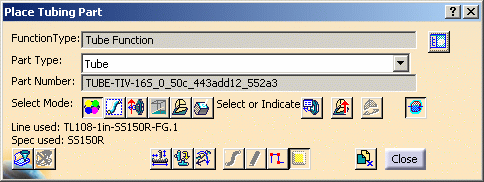
- Select or Indicate: This is the default selection and allows you to select or indicate a placement location.
- Select Run Only: You can only select a run.
- Select Connector Only: Allows you to select a part connector only. First select a part - all connectors display - then select the connector.
- Indicate On Local XY Plane: You can select a location that is on the XY plane of the local axis of the document.
- Indicate on Compass Plane: You can select a location that is on the compass plane. If the compass is inactive then the local plane will be used.
- Select Surface: Select a surface and then select a location.
- Select part to display connector list: This button allows you to use a dialog box to select the connector on which to place a part, and is useful in busy documents. Click this button if you want to select the connector on which to place your part by using a dialog box, instead of selecting the connector in the viewer. With your document open, select the part you want to place, click the Select part to display connector list button and choose the part on which you want to place your part. A Selected Part dialog box will display, showing all the connectors on your selected part. The selected connector will be highlighted, and will be orange in the viewer. Select the connector on which you want to place your part and click OK.
- Use Compass Z for Placement Up Orientation: The part will align itself with the compass Z direction, and not the default 'up' direction of the part. In the image below the valve on the left shows the default up direction, the valve on the right aligns to the compass Z direction.
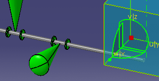
- Place at the Current Compass: This allows you to place the part at the compass location. The button is available only after you have moved the compass. To use, select your part, move the compass to the location where you want to place the part, and click the Place at Current Compass button. The part will place at that location.
- Ignore Compatibility Check with Neighbors: When you click this button you can place bendables and stretchables without invoking compatibility rules. NOTE: This button changes a Tools > Options setting (under Equipment & Systems > Design Criteria). However, this function depends upon a project resource management entry "Ignore Neighbor Compatibility", which takes precedence. Certain options (e.g. Options 0 & 1) you define for this resource in the PRM file will result in the button being grayed out.
The multi-place function applies to one run. If your run is broken, and you use the multi-place function, it will apply to a single run. If the Break Run at every placed part option is checked then the multi-place function may not work. To check or uncheck the option go to Tools - Options - Equipment and Systems and select/unselect the Design Criteria tab.

- The Override button brings up the Manage Override Parameters dialog box, allowing you to change attribute values.
- The Flip Part button allows you to flip parts that can be flipped, such as a reducer.
- The Move/Rotate button displays the Move/Rotate dialog box, allowing you to manipulate the part.
- The Tube Selection Shortcut button is a shortcut that lets you select part type.
- The Change to Schematic Mode button lets you toggle between schematic and non-schematic mode. You will exit the command when you click this button and need to click the Place Part command again.
- Click the Spec Driven button if you want part placement to be specifications driven.
- The Close button exits you from the command.
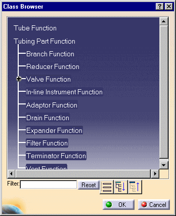
Note: You can choose to display the class browser expanded, as shown above, or collapsed, by using a setting. To display it expanded, go to Tools - Options - Equipment & Systems, click the Design Criteria tab, and check the option Expand Class Browser. Uncheck it to display it collapsed.
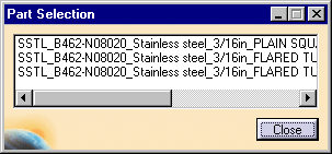
If the part you want to place can be created as a light object, you will be able to differentiate between heavy and light sample parts. Heavy parts are identified by the letters HV in the part name. Light parts do not have any designation.
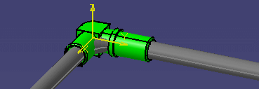
You can choose to display or hide a "preview" of the part you are placing. To do this click on Tools - Options, select Equipment & Systems and the General tab. Check or uncheck the box Display image while placing catalog object in 3D viewer to obtain the effect you want.
By default, when you click (in free space) to place a part the center of that part will be placed at that location. The center is determined by the application by drawing a box around the part and selecting the center of the base of the box. You can also choose to place the origin of the part at the point where you click. To do this click on Tools - Options, select Equipment & Systems and the General tab. Check the box Place at component's origin when placing in free space.
After you move or modify a run or
part, click the Update Part button
![]() and select a part to
update that part, or select the run to update the run. You only need to do
this if the application does not update the object.
and select a part to
update that part, or select the run to update the run. You only need to do
this if the application does not update the object.