Placing Parts Using a Schematic
|
|
This task shows how to place equipment and parts using a schematic drawing. The procedure below describes placing equipment. The same method is used for placing parts. | |
|
|
You must follow the parts
placement order described in Schematic Driven Design. You must also set the
Schematic Driven flag described in the same section.
Beginning Release 15, 3D versions of runs must be 'associated' with the corresponding schematic, if you want to do schematic driven parts placement on a run. Runs will automatically be associated if you create them in Release 15 using a schematic. Runs that are not associated with the corresponding schematic must be associated by you - if you want schematic driven parts placement. If you change a schematic after creating a run, you should associate them again. See Analyzing Schematic Driven Design to learn how to do this. In order to place equipment you must be in the Equipment Arrangement workbench. To create a run and place parts you should be in the appropriate workbench. If the Function Driven flag in the project resource management file is set to 2, then schematic driven parts placement will not be possible in Equipment Arrangement. |
|
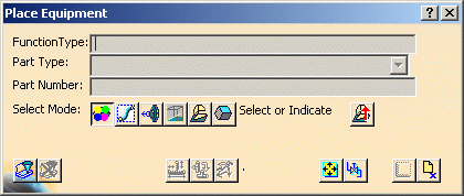
| 1. | Click the Place Equipment button
If your resources are stored in ENOVIA then you first need to import it using procedures described in the ENOVIA section of this manual.
|
|
|
|
2. |
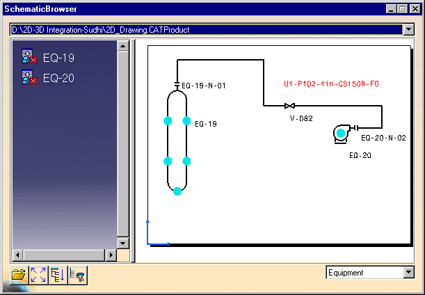
Click the equipment you want to place first,
in this case EQ-19.
NOTE: Use of the Select Mode buttons is explained in Placing Parts. Refer to that task.
|
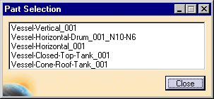
| 3. | After you define the Part Type, the Part
Selection box will display and you can select a part. If both Function Type
and Part Type were defined then the Part Selection box will display when
you click on any equipment in the schematic and you can select the part.
|
|
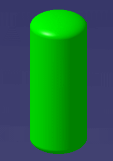
| 4. | Click in your 3-D document to place the
equipment.
|
|
|
|
Parts and equipment have "ordered placement"
capability. To give an example, in the image below if you have placed the
valves 1 and 3, then valve 2 will only place between those two. You will
not be able to place it to the right of valve 3.
|
|
| 5. | Using the procedure described above, continue
to place all equipment and nozzles you want to from the schematic.
If you assigned names to connectors when you added them (both in the 3-D and schematic application) then your 3-D nozzles will be placed at the correct connector on the equipment - the nozzle will place on the connector which has the same name as the connector in the schematic application. |
|
|
|
||


