-
Expand the specification tree and select the Italian Marble material.
-
Select Edit > Properties (or use one of the other methods detailed in About Material Properties) to open the Properties dialog box.
-
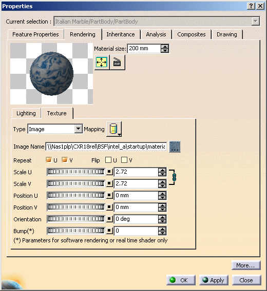
Click the Texture tab in the Properties dialog box:
-
In the Image Name box, navigate to locate the desired image, and click OK to map it onto the preview element as the texture.
In the example, we choose the italian_marble.jpg image available with the default catalog. The following image formats can be used: - tif: TIFF (Tagged Image File Format)
- rgb: Silicon Graphics 24-bit RGB color
- bmp: Microsoft Windows Bitmap Format
- jpg: JPEG (Joint Photographic Experts Group)
- pic: Apple Macintosh Format
- psd: Photoshop Format
- png: Portable Network Graphics
- tga: Truevision Targa file format.
Depending on the document environments (i.e. the method to be used to access your documents) you allowed in the Document settings, an additional window might appear simultaneously to the File Selection dialog box to let you access your documents using an alternate method:
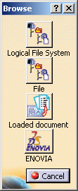
In our example, four document environments have been allowed among which the DLName environment. If you want to access your texture files using DLNames, just click the Logical File System button: this opens a specific dialog box dedicated to the DLName environment.
For detailed information on this dialog box, refer to Opening Existing Documents Using the Browse Window.The Type box indicates the type of texture you applied: - Image: identifies materials with a texture. In that case, the corresponding image name is displayed in the Image Name box
- None: identifies materials with no texture such as metals.
A preview area, in which different mapping types can be visualized, is also available:

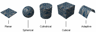
These different mapping types are available to let you select the most appropriate mapping for the shape of the geometry: - Planar Mapping is similar to a slide projector (a picture on a wall, for instance). You can use it for textures with two privileged directions such as Chessboard or Wall of Bricks
- Spherical Mapping is similar to a painted light bulb. You can use it for textures that do not have a privileged direction such as stone or raw metal
- Cylindrical Mapping is similar to placing a label on a can of food. You can use it for textures having a privileged direction such as shiny metal or marble
- Cubical Mapping is similar to wrapping a box
- Adaptive Mapping lets you choose between two mapping types: Automatic or Manual.
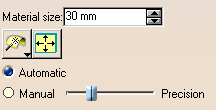
The Automatic adaptive mapping automatically creates a planar mapping on each object face.  Manual adaptive mapping gathers together faces which
have close normal vectors. For each group of faces, a unique planar
mapping is applied. The precision value defined using the slider
modifies the tolerance used during the grouping process: the lower
the precision, the more faces with greatly different normal vectors
are gathered together. This manual mapping enables textures to
cross slightly sharpen edges, thus providing higher visual quality.
This mapping type is especially relevant for materials with no specific orientation such as leather or wood for example.

Manual adaptive mapping is available for Real Time Rendering 2 users only If you try to select it when working with Real Time Rendering 1 or Photo Studio, it will automatically switch to Automatic adaptive mapping. Manipulations are available within the preview area: zooming in and out, rotating the support, translating it. Click the Fill All In Preview  button to reframe the support within the preview area.
You can also manipulate the object (i.e. zooming in/out, etc.) directly in the geometry area while displaying the Properties dialog box either by double-clicking the material in the specification tree or by right-clicking the material then selecting xxx object > Definition. -
If necessary, change the material size to adjust the scale of the material relative to the part.
-
Define the image repetition along U and V, as well as its scale, its position and its orientation:
U and V correspond to parameters of the local parametric surface. - Repeat U, V: lets you specify whether or not you want the texture repeated ad infinitum along u- and v-axes
- Scale U, V: determines how the texture is stretched along u- and v-axes
- Position U, V: determines the position of the texture along u- and v-axes. By default, the image is centered
- Orientation: defines the rotation of the texture on surfaces.
-
 Use
the Flip U and Flip V check boxes to invert the
material texture along U and V axes.
Use
the Flip U and Flip V check boxes to invert the
material texture along U and V axes.You can click the Link U and V scales  button to resize U and V proportionally. This is especially useful
for square shapes, the Floor material for instance.
Note that when this option is on, the Scale V box is grayed and the button changes to .
.The Inheritance tab displays information about the material inheritance mode and the checkboxes are grayed out until a material is applied. -
The Bump slider lets you create a bump mapping effect when applying 2D textures. Bump mapping is a lighting surface effect, based on a texture, that locally modifies the geometric aspect of the basic object by means of an artificial perturbation of the surface normals. These normals are vectors perpendicular to the surface defining the orientation of the surface.
But keep in mind that bump mapping cannot be visualized in real time display, it is used for rendering purposes only.
As of V5R16 and provided that your hardware configuration supports it, the CgFX technology which lets you visualize a material with both a texture and a bump effect.
Below are two pictures showing a material onto which a texture has been applied. On the left, CgFX technology is not used and no reflections are displayed whereas on the right, CgFX technology is activated and reflections are displayed: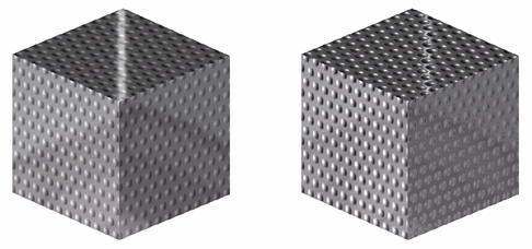
-
Click the Analysis tab if you want to edit the material physical properties, such as the density and so on. These data will be used for calculation purposes in the Version 5 - Generative Structural Analysis User's Guide.
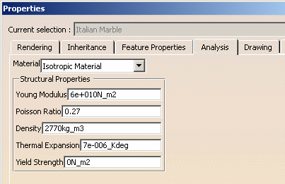
Note that appropriate licenses are required to use this tab. -
Click the Drafting tab if you want to set the pattern used for creating section views or section cuts:
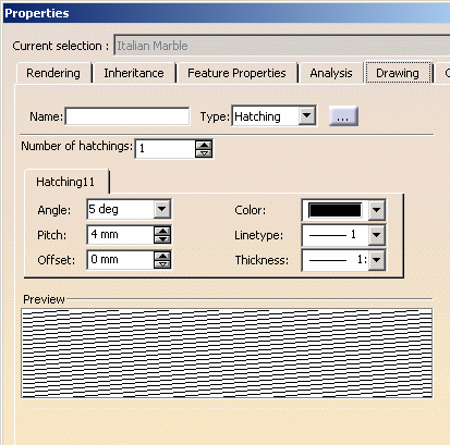
When a material is applied onto a product, the pattern information is used only for the part(s) contained in the product.
For more information, refer to the Version 5 - Generative Drafting User's Guide.
Note that appropriate licenses are required to use this tab. -
Click OK (or Apply then OK) to validate the material texture definition.
The material icon reflects the material as defined. Note that there is no specific order for defining parameters.
-
Position the material interactively using the 3D compass as explained in Applying a Material.