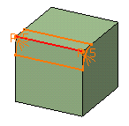
This task shows how to create a standard variable radius fillet. After performing the scenario, see also Variable Radius Fillets Using a Spine.
-
Click Variable Radius Fillet
 .
.
The Variable Radius Fillet Definition dialog box appears. -
Select the edge to be filleted.
You can define variable radius fillets on closed edges. See Variable Radius Fillets Using Closed Edges.
The application detects both vertices and displays two identical radius values.
The icon available after the
Edges to fillet field lets you edit the list of the faces to be
filleted. For more information about that capability, see
Editing a List of Elements.
Optionally, click Preview to see the fillet to be created.
|
|
-
Enter a new radius value to simultaneously change the radius of both vertices. For example, enter 12mm. The new radius value is displayed on both vertices. The preview is modified accordingly.
You can use the radius value R=0 to create a variable radius fillet.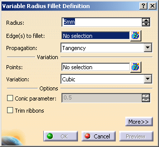
Two propagation modes are available:
- Minimal: the application does not take any
tangencies into account. If filleted edges overlap, the application
trims the fillets and creates a sharp edge. For the purpose of this
scenario, keep this option.

The edges tangent to selected edges can be taken into account to some extent. The application continues filleting beyond the selected edge whenever it cannot do
otherwise. - Tangency: tangencies are taken into account so as to fillet entire edges. If you set the Tangency mode, the Trim ribbons option becomes available: you can then trim the fillets to be created. For more, refer to Trimming ribbons.
- Minimal: the application does not take any
tangencies into account. If filleted edges overlap, the application
trims the fillets and creates a sharp edge. For the purpose of this
scenario, keep this option.
-
Click the Points field then a point on the edge to be filleted.
The application displays the radius value on this point. Note that to remove a point from the selection, you just need to click this point.
You can also add points by selecting planes. For more information, refer to the end of the task. You can add as many points as you wish. -
Enter a new radius value for this point: enter 4. The new radius value is displayed.
This is your preview: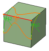
-
The variation mode is set to Cubic: keep this mode. To see the Linear propagation mode, refer to More About Variable Radius Fillets.
-
Click OK to confirm the operation.
The edge is filleted. The specification tree indicates this creation.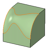
-
To edit this fillet, double-click EdgeFillet.1 in the specification tree.
-
To access additional options, expand the dialog box by clicking More..
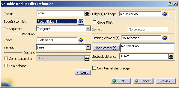
-
Click the Limiting elements field and select Plane.1 as the plane that will trim the fillet.
An arrow appears on the plane pointing to the portion of material that will be kept.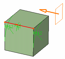
-
Click this arrow to reverse the direction and therefore specify that the portion of material to be kept will be the opposite one.
-
Click OK.
The variable radius fillet is trimmed to Plane.1. The final part looks like this: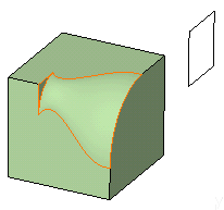
- If the conic mode is activated, the field and the option cannot be selected.
Variable Radius Fillet Dialog Box
This is the fillet you would obtain using the Linear
variation mode. Examine the difference!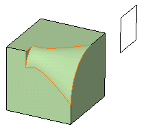
Points
- Contextual commands creating the points you need are available from
the Points field:

- Create Point: For more information, see Creating Points
- Create Midpoint: creates the midpoint of the line you select
- Create Endpoint: creates the endpoint of the line you select
- Create Intersection: see Creating Intersections
- Create Projection: see Creating Projections
- Create Plane: see
Creating Planes
If you create any of these elements, the application then displays the corresponding icon close to the Points field. Clicking this icon enables you to edit the element.
- To add additional points on the edge to be filleted, you can also
select planes. The application computes the intersections between these
planes and the edge to determine the useful points.
In this example, three planes were selected. Now, if you move these planes later, the application will compute the intersections again and modify the fillet accordingly.
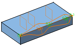
- Points can be added too by selecting 3D points.
No Internal Sharp Edges
When computing variable radius fillets, the application may generate unexpected sharp edges when the surfaces to be connected are continuous in tangency but not continuous in curvature. In order to improve your design, just select No internal sharp edges. This removes all possibly generated edges.
Note that this option does not work with Keep edge,
whatever mode you are working with (explicit
or implicit mode). For more information, see
Keeping Edges.
Edges to Keep
Specifies the edges which you do not want to fillet while running the
fillet operation on the edges of interest. For details about Edges
to keep, see
Keeping Edges.
|
|
This option is available only if you are defining a constant
edge fillet using Variable Radius Fillet
|
Blend Corners
Blend corners option, see
Reshaping Corners.
Variable Radius Fillets Using a Spine
There may be times when you need to fillet consecutive edges with no tangent continuity but which you want to treat as a single edge logically. You can do this by using a spine. Compare the fillets below:
Standard Fillet
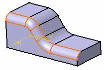 |
To fillet the edge, the application uses circles contained in planes normal to the spine. It is then possible to control the shape of the fillet.
The spine can be a wireframe element or a Sketcher element.
the Generative Shape Design product license is required to access this capability.
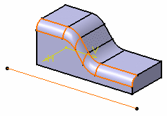 |
Variable Radius Fillets Using Closed Edges
- The application defines a default vertex on closed edges when applying the Variable Radius Fillet command. To define your fillet, first of all you need to remove this vertex, and then use 3D points or planes only.
- The Linear propagation mode is not valid for closed edges and edges continuous in tangency.
Limiting Elements
-
It is possible to use one or more limiting elements.
- Contextual commands creating the limiting
elements you need are available from the Limiting elements
field:
- Create Point: For more information, see Creating Points
- Create Midpoint: creates the midpoint of the line you select
- Create Endpoint: creates the endpoint of the line you select
- Create Plane: see Creating Planes
- XY Plane: the XY plane of the current coordinate system origin (0,0,0) becomes the limiting element.
- YZ Plane: the YZ plane of the current coordinate system origin (0,0,0) becomes the limiting element.
- ZX Plane: the ZX plane of the current coordinate system origin (0,0,0) becomes the limiting element.
- Create Intersection: Creating Intersections
- Create Projection: see Creating Projections
- Create Join: joins surfaces or curves. See Joining Surfaces or Curves.
- Create Extrapol: extrapolates surface boundaries or curves. See Extrapolating Surfaces and Extrapolating Curves.
If you create any of these elements, the application then displays the corresponding icon in front of the Limiting elements field. Clicking this icon enables you to edit the element.
- You can create limiting elements just by clicking on the edge to be filleted. The application displays this element as a blue disk.
- You can select points as limiting elements.
These points must be located on the edge to be filleted and they must
have been created using the 'On curve' option available in the
Point Definition dialog box.

Interrupting Fillet Computations
In case you made a mistake when defining a fillet (wrong radius value
for example), you can interrupt the feature computation launched after
clicking OK, provided that the computation requires at least 5
seconds to perform.
When a computation exceeds 5 seconds, a progress bar appears and provides a
Cancel option. To interrupt the operation, just click that
Cancel button. This interrupts the process and then displays an
Update Diagnosis dialog box enabling you to edit, deactivate, isolate or
even delete the feature.
This capability is available for any types of fillet features you are creating or editing.
